Leaderboard


Popular Content
Showing content with the highest reputation on 03/10/21 in all areas
-
I'm a little lost Peter. While a skim reading of your treatise gives the impression that your explanation of how an electric motor works and how the back EMF is used to communicate the motor state to the ESC is generally accurate, the fact remains that you appear to be claiming that watts in don't equate to thrust out minus any heating effect in the motor, ESC and wiring - i.e. your previous claim that all of the electrical power used is turned to heat. This clearly can't be the case as the energy converted to thrust has to come from somewhere!4 points
-
Preparing the cowl for painting and Metalcoat application. The front portion roughly marked out with a Sharpie and flush rivets ground out with a small burr in a Dremel. Although they look large a practice strip of Metalcoat stuck over gives the right effect. Panel lines for the opening cowl doors are doubled up 1mm chart tape and the cowl catches have been cut from some silver sticky backed vinyl and framed with chart tape. Hopefully once sprayed will give the desired effect. The tape gets removed after primer but the silver vinyl remains.3 points
-
The engines have been sitting at the back of the bench and the tail section generally getting in the way under the bench which means there is only one thing to do! Focke Wolf Ta 154 mk2 There a bunch of improvements that will be incorporated although the main focus this time around will be: Build this as light as possible Increase the wingspan by a few inches Increase the horizontal stabilizer area by a little bit Incorporate an adjustable horizontal stabilizer (like on the plans) Thin the vertical stabilizer cross section and reduce the gap to the rudder Lighter version of the nose wheel retract Reduce the sheeting thickness as I'll be glassing it again Now don't get too excited as I will be cutting a loads of holes in most of the parts to get ride of some weigh before getting the glue out, but could not resist a couple of photos until I was evicted from the kitchen table. ? Now for a bit of detail The wood (ribs, bulkheads and spars) come out at a total weight of 961g which I'll weigh once I have thinned it out over the next couple of weeks + coupled with the thinner sheeting and other changes should get it down to a more comfortable wing loading.3 points
-
Got rear bearing out, Found in my box of bits an old type expanding bolt used to fix things into concreate. Once tightened in the bearing inner it gripped very well, a spin then made sure it was only holding in the bearing and not the casing. A dose of boiling water over the casing and then set up as in pic then two good taps had it out. The one with the blue pipe on it was a first attempt with a Rawl bolt but it did not grip enough.3 points
-
Completed and passed!.2 points
-
They all look quite long, even the shortest one noted on the Hamilton Standard Prop. Fibs all round then!2 points
-
Hi Tony, That there are the number of Spitfires, Hurricane's and 109's for us to see in the air and in museums today is very much down to the making of Battle of Britain and other films. Many airframes were brought out of deteriorating obscurity some to fly and others for static use and it was at that time the late 60's and the 70's that the warbird movement gained ground with air displays becoming even more popular and the publication of the then new Aeroplane monthly mag. The recent death of Conny Edwards in 2019 who was a pilot for the BoB film has brought a number of Buchon 109's and a Spitfire on to the restoration scene. The Spit was his to start, the 109's he had taken home to his ranch in Texas in as payment for his work on the film. He kept the Spit and a 109 airworthy for many years. Others were dry stored making the very good candidates for flying restorations today. Cheers John.2 points
-
Thanks gents. ? I love aeroplanes, always have. It's impossible for me to adequately express how little I care whether or not CGI can produce realistic imagery of elves, goblins and other entirely fictitious creatures, my interest is in how the aeroplanes look in a film and how they are portrayed. IMO CGI does a very much inferior job, compared to the assembly, choreography and filming of what was, at the time, over 100 real aeroplanes. Some of the flying scenes have more than 50 real aeroplanes in simulated battle. That Flypast article tells how in the first takes the Spitfires were not getting anywhere close enough to the Psychadelic Monster B-25 camera ship and subsequently the pilots were instructed to close within a few feet of their target. As Peter said, the film-makers had such luminaries as Robert Stanford Tuck and Adolf Galland as advisors, who both knew a bit about aerial combat. Even the scenes involving models - such as the simulation of the Stuka attack on Ventnor Chain Home Low radar station, ought to hold fascination for aeromodellers -despite the fact that the Stukas are models, rather than real Stukas. It's a credible representation - compare that to the horrible CGI in Pearl Harbor - the real aeroplanes in Tora Tora Tora! did a much better job, even though many of them were barely converted Harvards. Still preferable to CGI sprites turning in their own length and knife-edging between hangars. Save that nonsense for computer games where it belongs.2 points
-
All too easy to criticise old films in the light of what can be done today. 20/20 hindsight. A relative of mine was an aerial cameraman on BoB sitting in what would have been the rear turret on a B25. You might think the film is rubbish but he sweated and got air sick filming the scenes which some teenager experienced in CGI could replicate in a few hours. Give the film makers some credit for achieving what they did with the technology of the day. It is still a great story of the days in 1940.2 points
-
Have you ever wondered how many models you've built. I'm not one of those modellers who records every model he's ever built and who logs every flight but in an idle moment I made a list of all of the models which I've built. I built the first model when I was eleven years old, I am now seventy-three! I thought I'd built more but apparently not. Having said that I keep remembering other models which I have now have to add to the list! In my case it amounts to 28 models built from kits or plans plus a further 14 which I bought ready-made, some requiring considerable refurbishment. Three of these are yet to be flown. In addition I have assembled eight ARTFs four of them foamy electric powered models but we don't count do them do we! ? Awaiting their turn on the building board are eight kits and an ARTF B17 Flying Fortress. I won't live long enough to build them all. Anybody fancy a 1/6 scale Fokker DVII kit or a DB Sport & Scale 1/4 scale SE5. The Fokker is not the Flair kit but something rather more involved. Please bear in mind the cost of postage from France. PM me if interested for details. It's not that big a list compared with that of the aeromodelling journalist Peter Russell. His "363 Delta" was apparently the 363rd model he had built! Guess I like wine too much!1 point
-
Thanks for the help all. The bloke I got it off said it was half run in so will stick with 35:1 and check the valves every now and then. I'll grab some 2 stroke oil soon and give it a go! Mixed opinions on the engine so hopfully mine is one of the better ones!1 point
-
Well done BMFA, hopefully it will be a regular on the event list in coming years, i spent far more than anticipated today ? My purchases included a kit and strip balsa plus various sundry bits from SLEC, a 3D 1/4 scale pilot of myself from Scale Me Down, a number of model building tools and and some glass cloth and EZE Kote from Delux materials. Stocked up now for a good season of winter building.? Many thanks to the traders that were present over the weekend.1 point
-
Ply top decking trimmed to clear the cabane struts, happy with the fit now so tomorrow the covering can finally begin ? I will be using Polyspan with thinned non shrinking dope before painting. The top decking will get covered first followed by the rest of the fuselage, this will also be painted before the cabane struts are glued on as it will make it awkward to paint the area between them once in position.1 point
-
John, Thank you, you're a star. Still think the method / manual is very convoluted for what should be a simple drop down selection. Are manuals ever 'road tested' on a variety of end users(?). We're not all IT or PC wizards etc.! Yes, ink tanks are the way to go instead of cartridges, (even the cheaper non-manufacturer varieties). Meanwhile, I'm writing my own 'Janet & John' Plain English instructions for next time I want to print a booklet.1 point
-
Designed by Graham Dorschel. Not sure if he frequents this forum buts he's still flying.1 point
-
Did a bit of reworking of my charging station today. I've changed over from exclusively charging at the field, to now doing some charging at home. I still do charge at the field, but I now prep for going flying by charging at least a few packs, since it's now a much longer trip to my old club site. For my local club site I can also just take enough packs for half-a-dozen flights and not bother with charging at the field at all. I initially set up with a pair of Bat Safes for charging and continued to use my Lipo Sacks for storage, along with a pair of Sentry Fire Safes for some of the less frequently used packs. I was never very happy with having the Lipo Sacks sat on the bench though and then saw these steel cabinets on FB marketplace, which would fit nicely under the bench. After a bit of a false start I finally managed to collect one yesterday and it's ideal for the job. Bottom shelf takes the Sentry Firesafe with the rarely used packs. Top shelf takes the Lipo Sacks, separated into charged and discharged packs. So it's just a matter of grabbing the Lipo Sacks when heading to the field. The cabinet is vented at the back. Turnigy Reaktor and Graupner Unimat 14 chargers are mounted on the lids of the Bat Safes, fed by a pair of 20amp power supplies, NiMh charging is taken care of by the Graupner Ultra Duo 30 plus in the middle, for peak detect fast charging and the multiport Robbe Lader for receiver packs in my gliders. 1s cells can be charged either with the little E-Flite chargers on the shelf, or via the multi-cell board with the Reaktor. My field chargers are then free to stay in the flight box, so the workshop chargers don't need to be disconnected to go flying.1 point
-
Just as a bit of extra info, I have attached a photo which shows my early "sensored" brushless motor and ESC which I bought in the early/mid 1990s (alongside a brushed motor of similar vintage). The motor has hall effect sensors built in with 5 wires connecting the sensor to the ESC. I have seen our brushless motors referred to elsewhere as "electronically commutated DC motors", and that is actually a fairly accurate description. Dick1 point
-
Info at Sarik says it is for pusher or edf I will check with 4 Max for the appropriate edf unit1 point
-
In the 1920's or there abouts a black and white film was made about fighter pilots and squadrons ( Howard Hughes ? ? ) Of the first world war, showing dog fights. Some pilots were killed making that film... I bet older people who experienced the blitz get frightened again when they hear an air raid siren on a film, or bonfire night... Remember to get your poppy...1 point
-
Sorry, so next time I will post a book on my rubbish jokes so as not to offend,,,?1 point
-
Graeme. I have an NGH38 which runs great but you do need to make sure that the valve gear gets well lubricated. Assuming that the engine is already run in, you'll need a good quality fully synthetic 2 stroke racing oil. I use Mobil 2T racing but other brands are available. The recommended mix is 25:1, which is a lot of oil presumably due to the valve gear requirements. I have a few different makes of engine and I tend to run them all on the same fuel mix. Before I got the NGH38, I used to run them all at 40:1, but now I have settled on a compromise of 35:1. It works for me but I am always wary of under-lubricating the valve gear. If you only have the one petrol engine or don't mind having the special mix, I'd push it to 30:1 or 25:1. Before you start it, take the valve covers off and have a look at the valve cams and give them a good oiling (and adjustment) while you are in there. P.S. It's a great engine with a very distinctive sound and it will amaze you how little petrol it drinks. Edit - Correction. I've just looked at the manual and 25:1 is only for running in. 35:1 is the correct mixture for this engine once run-in.1 point
-
Thanks all. I realised that the outputs of the ESC are "chopped" DC, rather than a sinusoidal wave. I've seen the term sensor-less but never appreciated what it meant, so thanks for the insight. As you say Simon, they are true marvels of electronics. It's nice to know what's going on under the bonnet, but sometimes it's best to just put your foot down and drive.1 point
-
Carb kits normally come with bits you won't need, some bits are common to carbs other than yours, so don't sit scratching your head or thinking they've sent the wrong one Andy.1 point
-
Just in case anybodies interested, solved the problem. Two more ounces of lead in the nose. I know all the aerodynamics say it shouldn't mattelr. And I don't know why it does. But it does..... Now lands and flies much better. Maury1 point
-
Thanks John. The same subject drift occasionally happens at committee meetings and a quick prod back onto topic is needed.1 point
-
I read about the RCC in a recent Achievement Scheme email news letter a few weeks ago that I'm signed up to get. I took the on-line test there and then and passed it without a problem. I didn't bother to revise anything as being a club examiner I do keep up to date with what's going on. Examiner or not, it's worth doing the test and adding it to your BMFA profile, even if strictly speaking you aren't required to.1 point
-
Unmanned aircraft agreed, but biased towards drones which in our club we never have and are not allowed to fly. I would not be at all surprised if some examiners are lost, which is a shame. I would not bother with it, but for the fact we have a good bunch of lads in our club who need A and B testing from time to time.1 point
-
From the perspective of someone who has never taken part in an aerial battle (except a bout of mock combat with a friend in vintage gliders) I'd imagine the scenes depicted in the BoB and other examples such as Howard Hughes' Hell’s Angels - filmed with genuine WW1 aircraft and pilots and despite the awful acting) are far more realistic than some of the OTT CGI effects that I've endured in some recent films. I'm sure that nothing shown on a cinema screen could come close to the noise, smells, vibration, G effects, disorientation, fear and spatial effects that must have been involved but the BoB film was a valiant attempt IMO.1 point
-
Do you have first hand experience of air fighting then? Unless you know what the tactics are that are being employed it is very difficult to follow an aerial battle. The firing solution is achieved fleetingly while aircraft twist and turn or just turn as tightly as they can. That is difficult to depict but I think they did a great job in the film. Look at who they had advising them as well - people like McHaddie, Bob Tuck etc all BoB pilots. So, pleased you think you know better than them.1 point
-
My workshop conversion that was completed between the lockdowns uses an air source heat pump and an excess of efficient insulation to provide a comfortable environment in a large space within half of our outbuildings. We'd intended to extend the system to the other half of the outbuildings, but the lockdown scuppered that. I'm delighted with the system, it has hugely exceeded my expectations. The temperature control in the workshop and storage area is excellent, with the radiators on the lowest setting and the system has plenty of excess capacity to extend and add more radiators in the rest of the buildings. The key really is in the insulation though -which has the opposite benefit in the summer with super stable temperatures. That hugely reduces the amount of energy needed. Originally we wanted a ground source heat pump and underfloor heating, but when we investigated further it became apparent that the air source heat pump and wet radiators was the better option, since it didn't require major structural work in digging up a perfectly serviceable concrete floor over a very large area. I was sceptical, but the system has worked very well in the first year of operation.1 point
-
Thanks Matty, can we keep it on topic now please gents.1 point
-
Urban wind generation is a sure fire way to be hated by your neighbours and council alike, but thankfully there are better options now - for instance Ripple (where you own a portion of your own wind farm) is a very intriguing offering that I am looking into seriously at the moment, it’s a very interesting alternative for houses where solar PV, solar thermal or other generation technologies might be hard to do. If we are to hit global CO2 targets there is going to have to be 2 decades of incentives at least to get us over the line - yes there is uncertainty about the RHI at present, but without it who is going to install these alternative technologies? Taxing green tech would make zero sense at this point. Besides, if you’re taking very little net from the grid the the impact of “taxing” via your smart meter could only ever be fairly minimal. What would seem far more likely in the med/long term is higher taxation on fuel oil and gas to make the greener alternatives more financially compelling. Right now we are committed to this route as a family, but I doubt it will pay back in full for 10-12 years. If that remains the case only a small percentage of people will be able to make the switch to low carbon energy. Back to the thread topic, I will start another thread…1 point
-
I'm going with make sure the work piece is Clean, I buy none of the various chemicals described, Brillo pad, washing up liquid or similar, get it clean and you're most of the way there.1 point
-
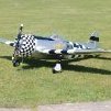
Lovely long dome nut from Jon on my P47. I also wasn’t convinced I could get sufficient torque with a rod through the hole, as it isn’t that big, so I drilled out a hollow so it tightens over the regular prop nut as you mentioned in your post. Works great and I like to think of it as a lock nut for added security. BTW Tim, since you saw it’s shaky maiden it is now well sorted and a brilliant model to fly.1 point
-
The Henley Solon I've had for about 60 years is 125 watt and has a very big copper bit. It takes a while to get up to temperature but, once there, it does the job. I once used it to resolder the fuel tank of my 1932 Scott TT Replica with no problems (It was a squareish tank that was soft soldered when manufactured.) As with all soldering, the 'secret' is cleanliness and getting the joint to the right temperature before applying the solder with a suitable flux. As my dad always said, apply the solder to the joint not to the iron - he also said never to carry the solder to the joint on the iron when soldering small electrical components, but I often ignored that ? Geoff1 point
-
Martin, I have used Dubro DUB 257 heavy duty flat hinges with removable pins for my flaps. The full size had a huge rotary hinge with a universal joint at the split. I was looking at some photos yesterday and also noticed an overlap at the split which I haven’t as yet replicated (inner flap overlaps outer). I may be able to let and blend in a strip of litho plate to add the detail but probably better to set the servos up first, otherwise they could fight against each other if not perfectly synchronised. BTW your baby talc/dope/primer sounds like proper modellers alchemy.1 point
-
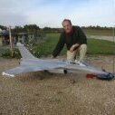
For your delight and delectation, my first own-design scale model. FVVS J-22. A swedish fighter of little renown. 44" span, AUW 2lb 12Oz (wing loading 18 Oz/ Sq Ft). Power 3536 1200kv on a 10x5 and 3S 2200MAh Pack giving approximately 400W Retracts fitted, retracting rearward. I opted against twist/ turns because I fly my retract fitted models from a bumpy strip and take off on the wheels, but belly land. The wheels stay slightly proud when retracted, which is not scale, but is a nice shock absorber for landing, and a nice grip if I hand launch. Thanks To Richard Wills and Peter Miller for their design ideas, advice and inspiration! Just the maiden now. And of course, this is the only one, so no point asking anyone else how well it flies! Graham1 point
-
Tacho: Taco: ?1 point
-
Personally I don't think this thread is the place for detailed discussion of electrical theory. It is not at all what the OP asked. A new thread would be the place to air different views on watt meters and to debate principles of physics.1 point
-
Before this thread finally disappears into a misty oblivion may I just take this opportunity to bump it up and say that there are still one or two questions I’d like to ask regarding the wattmeter and the useful information that can be given by it’s readouts. I’m not very familiar with it as I’ve never seen one, at least not the kind that modellers use anyway, so I’m thinking it may it may help to avoid making mistakes in any future posts. To show the greatest respect to Tony’s Original Post and taking Bob C’s Good Idea firmly on board as well, would it then also be an alternative plan if maybe one of the moderators could be persuaded to fire up a new thread, say something along the lines of 'Watt difference does the odd volt or amp here and there make to anything’ perhaps, so that all this stuff can be discussed at leisure in an amicable fashion and any folks not interested needn’t even bother to open it. I”d be more than happy to include a disclaimer with any of my posts saying that these are just my ideas and may not necessarily be the true facts etc. PB1 point
-
Hi Matty, Thanks for your answer again and I do apologise for not being able to get back any sooner. But with the greatest respect I’m afraid I still have a few problems with it so perhaps I can explain how I think an electric motor operates. When a conductor is moved through a magnetic field a voltage appears on the conductor. One situation that affects this voltage is the speed at which either the field or the conductor is moving, in general the faster the speed, the higher the voltage. So this voltage appears on the motor’s winding all the time it’s turning, it’s called the back emf - electromotive force or sometimes motional force, I guess because it’s facing back toward the incoming supply voltage in a mirror image. The back emf directly opposes or cancels out the supply voltage all the time to a greater or lesser degree but can never equal or exceed it. If I might borrow your example for a moment (with no prop on) then at the moment we apply the full supply voltage the motor is stationary and this voltage will appear on the motor’s coils, the current will be at a maximum and so will it’s accompanying magnetic field. Therefore the deflecting action between the magnetic fields is also at a max., the motor starts to turn and as the speed increases the back emf also increases proportionally on the coils and opposes and reduces the supply voltage that is applied to them and in turn also reduces the current flow and it’s ever present magnetic field; eventually to the point where the magnetic field interaction can just hold the unloaded motor’s speed steady. If it were able go any faster the back emf would equal the supply voltage, there wouldn’t be any current and the motor couldn’t run, an impossible situation to arrive at. Checking the wattmeter, we find the ammeter is reading this small amount of current, the least it will ever be. But to check the speed of the motor at this point I have to use a rev counter, my problem throughout this saga has been that I’ve never been able to understand how I can use a wattmeter to do this. When I do check it I find it is invariably reading the advised unloaded revs. But I have found more than one that is completely different. If I now fit a prop on this will load the motor by some definite amount and therefore it will just simply reduce the amount of rpm the motor can now achieve. These will be definitely less than the unloaded rpm so this in turn reduces the back emf and thus increases the voltage applied to the coils and therefore the current and magnetic field strength. That increases the deflecting force of the magnetic fields by the exact amount to maintain this new speed. This action is completely self regulating for any increase or decrease in load however small. We now have three separate voltages, the bench supply, the back emf and the bench supply minus the back emf, let’s call this one the power voltage. It’s this power voltage that’s always applied to the motor’s windings; if the motor is running within it’s normal limits the power voltage will generally be quite low because the back emf is fairly close to the supply voltage and therefore the current flow will be within spec. But if we were to fit larger and larger props, steadily increasing the load, the motor's rpm would become less and less, the back emf would also become less and less allowing more and more power voltage to be applied to the motor’s windings until ultimately if the motor couldn’t turn at all it gets the full supply voltage with maybe smoke signals to indicate that this has happened. I’m sure very few few folk will ever get into this situation though, but a crash with the prop stuck in the mud and the throttle still full up can, and does, occasionally happen…… I find it very difficult indeed to see how the back emf can be related to the rotary output other than how I’ve described. It has no circuit so no current or associated magnetic field. It simply reduces or increases the supply voltage which reduces or increases the current flow to the motor. One point to note perhaps, every time the increased load reduces the back emf by a factor of two this doubles the power voltage and thus the amps flowing so the power dissipated goes up by a factor of 4. But for the rest of the circuit the supply voltage doesn’t change so these watts only double. This can only go so far though, when everything comes to a standstill but it’s still powered up it’s the total circuit resistance that’s the final limiting factor. Not sure about the ESC driving the motor either, in my view rather more like the other way round. If we momentarily call it the Electronic Switching Commutator it may be a bit clearer. The brushed motor’s mechanical commutator is synced to the motor’s speed by simply being part of the armature and turning at the same speed, so it has to do the switching and 180 degree current reversal at the correct time whatever the load and speed. I don’t know very much about ESCs so I’m pretty much guessing here that the motor and ESC are synced and switched by the back emf that’s present on the windings that are not switched on at any one time in the cycle; So by the same token this also has to do the switching and current reversal at the correct time. I hope it’s possible to see from this tome why a low resistance all round is so important, the Holy Grail and all that stuff…. Re the previous ramble about supercooling, there maybe yet some truth in the old proverb - There’s many a true word spoken in jest… First this: An article I noticed recently said that someone, I think it’s the Danes, have erected a small wind farm using supercooled generators. They are claiming a one third increase in output together with a one third reduction in size as well. Very little other specific detail though; I looked for any indication as to how much of the extra power delivered needed to be fed back to maintain the low temperature, particularly in times such as recently with extended periods of no wind and warm sunshine but they’re not saying. Do they switch the fridge off or just leave it running I wonder… Also it’s one thing to build a magnet with no moving parts, how much thought must have gone into the materials used in making bearings etc. I guess if they get a result we shall see more about it, if not it will probably just quietly fade away. So then a googled copy and paste from Wiki: A superconducting magnet is an electromagnet made from coils of superconducting wire. They must be cooled to cryogenic temperatures during operation. In its superconducting state the wire has no electrical resistance and therefore can conduct much larger electric currents than ordinary wire, creating intense magnetic fields. Superconducting magnets can produce greater magnetic fields than all but the strongest non-superconducting electromagnets and can be cheaper to operate because no energy is dissipated as heat in the windings. They are used in MRI machines in hospitals, and in scientific equipment such as NMR spectrometers, mass spectrometers, fusion reactors and particle accelerators. They are also used for levitation, guidance and propulsion in a magnetic levitation (maglev) railway system being constructed in Japan. Then I read that a Swedish gentleman had achieved superconductivity at a temperature of about minus 21 degrees C; little more than a freezer. No details on conductor material (or anything else) but if it could ever be forged into an electromagnet think of the possibilities. After all a motor might be called the Siamese’d twin of an alternator. And now Ford have announced they are investing $11.4billion into new electric car and battery making plants, I’d be very much surprised if supercooled motors to power them aren’t at least in the line of consideration at some point. Finally the last chapter here is left to come, measuring the mechanical rotary action of the motor. I’ll kick it off by just saying that I think this is done by a dynamometer or similar, this measures the force of the deflecting action of the magnetic fields at the same time monitoring the rpm with a rev counter. Like the electrical watt the mechanical watt is also a derived function so it multiplies the two results together at various rpm to plot an output power curve. NB I think ‘deflecting action’ can probably be translated as an ‘attraction, repulsion or twisting’ force according to the orientation of the magnets at any one time. Or perhaps just simply as torque. I may have to go AWOL again for a while soon, so reply times could still be erratic, sorry. PB0 points