

John Rickett 102
-
Posts
240 -
Joined
-
Last visited
-
Days Won
10
Content Type
Profiles
Forums
Blogs
Gallery
Calendar
Downloads
Everything posted by John Rickett 102
-
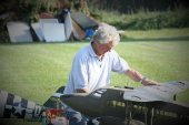
If it helps, here's a picture of Laser 50 and 61 all bought around 1992. The outer ones are the 50s.
-
I was surprised to learn that its 18% scale, throughout the build thread I had assumed it was at least 20%. I’m even more impressed you have been able to make all that detail at such a small scale. That’s not meant to sound disparaging, far from it, from my limited experience the smaller the scale the harder it is to create realistic detail, so well done. Inevitably all the additions were going to have a weight penalty but if you are happy with the scale performance, you’ve achieved a hard to reach goal, so again well done.
-
This has been a fascinating thread to read and I congratulate you on the scale fidelity. You mentioned right at the start that the model construction was actually some time ago, what scale/span did you settle on in the end and what was the final weight? Did the Laser 70 live up to expectations as an adequate power source for the size of model? Perhaps I'm jumping the gun and this will all be covered later..........
-

Laser Engines 40th Anniversary Fly-in
John Rickett 102 replied to Jon H's topic in Shows, Club Events and Competitions
Do we take from this that there is no need to book? Can anyone who wishes to participate just turn up with or without caravan/camper/tent. That's fine by me but it would be useful to know if there any preconditions, apart from a Laser engined model of course. I would hate to turn up and then found I've fallen foul of some little pre-requisite that everyone else knew about except me. -
Model Techics Fuel Formulas
John Rickett 102 replied to Andy Stephenson's topic in All Things Model Flying
I have no idea what it is but I believe it works, needles settings are noticeably less critical. In my view its a shame that Model Technics ceased trading but as with everything, we all have favourites. -
Model Techics Fuel Formulas
John Rickett 102 replied to Andy Stephenson's topic in All Things Model Flying
That must have been quite an old list as the popular TechPower and ProPower aren't included. Big Bang was probably the nearest to what is now considered Laser Low Oil fuel. -
The Saito ignition unit is by made by Rexcel - should be labelled as Rexcel on the reverse of the unit. When my Saito ignition unit packed up I got a Rexcel one from Just Engines and its works fine so I would expect the pick-up will also, though this is not definitive!
-
The main fibreglass components for the undercarriage are now complete and the trousers have been grafted onto the hatches. The trousers were tacked in position on the hatches with epoxy glue and then some narrow strips of 50gm cloth were laid over the joints and tucked in to make sharp corners. I’m quite pleased with the final shape and the strength of the joints, it wouldn’t have been possible to complete using wood. A concern in making the undercarriage was the possibility of not being able to fit or remove a whole undercarriage unit with the limited access available under the hatches and through the holes in the ribs. I was also initially concerned that a spat, once fitted, would prevent being able to remove a wheel – a wheel has to come out to allow access to the M5 screw which is attaching the wheel fork to the leg. Having now had to carry out this process a few times when getting the final position of each spat for drilling the holes, its actually quite straightforward - removing the M3 screws on either side of a spat allows the spat to slide up sufficiently to draw out the axle and release the wheel. Once the centre screw in the fork has been removed, the fork and spat come away. Removing 6 small wood screws releases the hatch/trouser and finally the undercarriage leg is exposed. There is then sufficient room to release the scissor, compression strut and the 4 bolts holding the main leg. The spat couldn't have been any narrower! Apart from a final clean-up, the fibreglass bits are complete and ready for painting, so its back to balsa bashing now although with spring showing positive signs of being here, the flying field may prove more attractive than the workshop.
-
The second spat is now out of the mould. Surprise, surprise it looks remarkably similar to the first. In case anyone's wondering what the blue lines are, they're where the fibreglass cloth was marked out prior to cutting with scissors. They actually help when laying the cloth to see where the overlaps should be. One weighs 74gm, the other 81gm so I didn't get it quite right but near enough to be sufficiently stiff for the intended purpose without an excessive increase in the overall model. The hope is still to achieve a finished model weight of 25lbs.
-
A baffle plate was made from 1/4" ply, covered in parcel tape and then given a couple of coats of release wax. 2 little brackets stop the plug from moving during the all important laying of the fibreglass. I forgot to take a picture but I tried decorator's filler to fill the inevitable gaps between the plug and the baffle and it worked fine. An initial layer of 50gm cloth to get the cloth right into the recesses was followed up with 5 layers of 80gm cloth. Once the first half of the mould had cured, the second was laid up against the first. Cleaned up and with some screws to hold it all tightly together, the mould is ready for waxing and then a cast taken from it. The mould halves were given 5 coats of release wax buffing in between. Its a pleasant smell so not a bad job to do! Again, following an initial layer of 50gm cloth a further 4 layers of 80gm cloth were applied and then in the middle bit, a layer of 100gm cloth to stiffen it. Here is the result straight out of the mould after 15 hours curing. A quick clean-up of the ragged edges and trial fit of the trouser.........I'm quite pleased with that. The spat will be left for another 2 days to fully cure before final shaping and rubbing down with wet n' dry. This will remove all traces of the release wax and provide a decent surface for a primer coat. Into mass production now with a second spat to be cast! Well not really, I'm hoping there won't be a need for more than two, though if there are accidents later on it will be a relatively simple task to mould another.
-
I’ve found that while Lasers are quite benign, the 180 is the one most likely to kick back when starting, this can either loosen the prop nut or throw the prop altogether. Having had a thrown prop damage a model, and the prop, on more than one occasion as well as having to search for the washer and nut, I thought there had to be a better way. As with most problems there is usually more than one solution to spinning the engine prior to applying the glow. The easiest is enlisting the assistance of a helper, however if (like me) you are often Billy No-mates, adapting the power source to automatically provide the delay is an alternative. For a number of years, I’ve preferred using a power panel as it allows for the current draw to be seen and adjusted for various plugs. One of these little timer modules can be bought for about £5 and has the ability to alter both the timing of the delay and the ‘on’ period from 0.1 sec to 99.9 seconds, which should cover most people’s requirements. I've set the delay before ‘on’ at three seconds, this gives time to pick up the starter and spin the engine, after which the glow comes on for 10 seconds. If the engine doesn’t fire up in 10 seconds then something is wrong, but a press again of the START switch initiates the sequence again. In addition to the timer module itself, all that is needed is a monetary switch to trigger the timing. I wanted the ability to bypass the timer and use the ammeter and rheostat to initially set the required current draw, so installed an additional switch to put the timer in or out of the circuit as required. My starter box is a bit Heath Robinson as I already had the panel and a 3300mAH 12v battery so just fitted the bits in the unused space, nevertheless it works and enables me to start a glow engine unassisted and without fearing a kick-back.
-
Artto, If you don't know anyone handy with a lathe, you could ask Just Engines to make you a shaft extender, with the hex end substituted for a Gipsy Major spinner shape. They are happy to undertakes one-offs and at reasonable prices. https://www.justengines.co.uk/?s=shaft+extender&post_type=product&v=79cba1185463
-
This is a Just Engines domed nut on a Laser 155. The original washer and nut are retained. It will accept a starter. The trick is to arrange the glow to come on after the starter has been applied and then there is no kick back.
-
A lucky find on the interweb was a picture showing the front view of the trousers. Only wide enough to clear the undercarriage legs of course and quite pointed. Not having access to the real thing, I have no way of knowing the true shape of them but followed the idea that they would be as narrow as possible. A plug was made from a scrap piece of blue foam which had been sculling around for years, covered in fibreglass cloth/resin and then a trouser cast on the outside of the plug. This was easier than having to make a female mould as well, hopefully no more will be required! With the trousers being parallel sided, I expected difficulty in releasing from the plug but the first has came out fairly easily. Good stuff Mequirar's Mirror Glaze. With a bit of luck I'll get away with being able to halve this for both sides but if not a second one will be simple enough to make. The trouser required a bit of rubbing down to get a smooth finish but still quicker than making female moulds. The initial plan had been to use the trouser as a means of covering the access gap needed to remove the main leg units. That idea was scuppered by the undercarriage mounting block being wider than the trouser. The problem has been resolved by integrating the trouser into a broader and longer hatch which extends to cover the compression strut fixing as well. To get the shape of the hatch, seven layers of 80gm fibreglass cloth were laid onto the wing and once cured, cut into two pieces (for left & right) and then the trouser offered up into position. It’s not scale but more or less out of sight and does provide room enough for the main leg and fixing bolts to pass through and at the same time allow sufficient access for an Allen key and spanner to work. Plan A was to glass the trouser onto the hatch prior to making the spats, then I thought better of it as the trouser has to be perfectly aligned if the spat is to slide over it freely as a working undercarriage. I thought that if the spat was to hand then I could line it up and the trouser at the same time. I was only allowing for a gap between the spat and the trouser of 1/16” all round, so not much leeway for error. On then to making the spats - again a plug had to be made using 1/8 liteply to achieve the shape which was then blocked with the core of Recticel insulation board. This foam is much easier to sand than blue foam, possibly too easy, so light pressure only. The pictures show the plug after sanding to shape but prior to glassing. The plug was glassed, first with 50gm cloth to seal the foam and then a layer of 80gm to add some resilience to the rather weak Recticel. This time I’m making a female mould as I don’t like the idea of doing excess damage to the plug releasing the first spat before the second one is moulded. The picture shows the glassed, rubbed down and touched up (filled with Isopon) plug, ready for laying of the first half of the mould.
-
As an aside, Fighteraces are also stockists of Klasskote, which is definitely proof against model fuels. Unfortunately its only sold in a limited range of colours and batches can have significant colour differences, so if ordering make sure you have enough for the job. What is good is Klasskote Clear, which is available in gloss, stain and and matt. If you finish a model, complete with masked lettering and transfers, which all have varying degrees of glossiness, a top coat of the Clear will make everything the same gloss, or lack or it. I've found this much better than car refinishing 2K matting agent which has to be mixed and will show up more matt when a previously sprayed area is sprayed again. In other words its difficult to get consistent results, whereas Klasskote is consistent. Now back to balsa bashing....
-
In my eagerness to see if I could braze something as small as a lug, I didn't take any pictures until the first support was completed. To prevent the lug slipping around while applying heat and silver solder, I thought the cross halving method (well that's what I was taught its called in woodwork at school) would hold the required position and add strength. Always remember to cut on the right side of the line! I cut this off a bit short but it will do the job.
-
That's what I had done the first time Ron using 3mm aluminium (see preceding posts) but that put both forks in a different plane so I couldn't remove the strut once the leg was bolted tight. Brian West suggested this method which has worked.
-
Following Brian's suggestion of a brazed lug set at 90 degrees, the metals scrap box was raided for some 3mm strip (for the lug) and 2mm strip (for the base). A bit fiddly but that's one done. I got the hole a bit close to the base so had to grind off the corners of the fork, not very elegant but it won't affect the strength. Thanks for the suggestion, a much better solution.
-
Brian, Well done, putting the hole at 90 degrees is a very good idea - now why couldn't I see that at the time....... The wheels are Fema, available in Britain from Fighteraces. They are sturdy, not excessively heavy, have a steel tube for the axle so can carry quite a weight and don't get sloppy.
-
The main undercarriage units arrived a few days ago. These were custom made by John Brookes and excellent they are too. There is minimal frontal area to allow the spats to be as narrow as possible; this was one of the ‘cleaning up’ improvements with the Vega Gull in order to reduce drag. For the model John has also incorporated an internal leg length adjustment so that there is some latitude with the mounting height which then enables the correct leg length to be achieved. The fixed portion of each leg is machined from solid and incorporates a lug for a rear bracing stay fixing. The legs are hung off the front spar using 1/8” ply web plates front and rear with a ½” ply crush plate in between. I’m confident this will stand up to all but my most ham-fisted of landings. A short compression strut, attached to the mid spar, should help resist the landing loads. The forks are the aluminium ones from SLEC, tapped M3. Once this was assembled I discovered that with both pins removed, the strut will not release from either lug - there isn't enough freedom of movement to make either end swing clear, so the whole leg has to be slackened to gain clearance. More by good luck than judgement, the M3 x 45mm mounting screws will just draw back far enough to release the leg. Hopefully removal won't be a frequent affair, as once the wing is sheeted there is going to be a lot less access room. Plan B is to omit sheeting over the area which will be occupied by the trousers. Unfortunately, in a way, with the units enclosed in spats and trousers all the beautiful machining will be hidden but at least we know its functional!
-
The cockpit area has been progressed although the windscreen panels have proved to be particularly troublesome, there are five panels on the Vega Gull, the central panel was added apparently when the design changed from the Gull Six. The Vega Gull was widened 6” to allow 4 occupants in a conventional square pattern instead of the 3 staggered places on the Gull Six. The central panel was quite easy but the others caused problems. The outer panels are straight at the bottom whereas the cowl/forward fuselage area is curved. I had three attempts at making front formers until I got something which blended in to give the correct shape to the bottoms of all the panels. From photos its looks as if the main window framing is about 1 – 1 ½ ” so laminating to achieve ¼” to 3/8” seemed about right. Above the windscreen is a curved panel, I suppose to flow the lines from the straight windscreen to the straight cabin top. The two main components which follow the lines of the central panel were laminated from cut down spruce and cyparis strip. A bit tedious but achieves the curve without inducing stresses into the rest of the windscreen. These were then pegged into position using 2mm carbon rod (that was all which fell to hand!) rather than just rely on butt joints. The inside of the fuselage cockpit area has now been sheeted in 1/64" ply. I've tried coloured card in the past and while it initially looks the part, over a short time it absorbs moisture causing it to sag and buckle. Using ply should be stronger and help tie in the cockpit area to the engine bulkhead. John Brookes has been as good as his word and made a lovely sprung and steerable tail wheel assembly. The spring fully compresses at about 10lbs so should stand up to some of my bouncier landings. Captive nuts have been fitted to the tail post to aid future access.
-
David, thankyou for supplying the Hyperflight link, now I understand how the system works.
-
The canopy frames have taken a while to get right. At first I thought I could laminate a whole former around a template with strips of cyparis, but by the time I had glued the third strip it become obvious that it was too floppy and may not hold two doors which will have to be hung off the front former. That Idea was scrapped and I raided my stock of spruce, which although heavier is also stronger and less whippy. Spruce won't bend round tight curves so a combination of scarf joints and laminated spruce for the top curves achieved the final result. The former shown is the rear canopy frame (5 laminations) with a layer of cyparis top and bottom. The rear former is inclined rearward 17 degrees so I knew there would be a need to sand away the edges to bring the top and bottom level again. Cyparis sands easily and the white colour allows for checking how the sanding is going when nearing the darker lamination beneath. Having got a couple of frames made and placed in situ, I went back to the idea of the long range tank. As can be seen in the picture below, my hopes that a tank would fit through the door have proved hopelessly wrong. According to the book, Straight On Till Morning, the adapted Vega Gull had six tanks, two in the inboard wings, two in the centre section and two in the cabin – yes, two in the cabin! The total tankage was 255 gallons. I can’t find out how much a standard Vega Gull carries, though the range is stated as 620 miles. Given that a Gipsy 6 consumes about 12 galls/h and the Vega Gull cruises at 130mph, then the fuel required is 57 gallons (to dry tanks). It seems likely then that the cabin tanks held about 200 gallons, this requires a volume of 32.1 ft3. At ¼ scale (divide by 64) this means my dummy tanks should have a volume of .502 ft3. The dummy tank which more or less fills the rear cabin has a calculated volume of .415 ft3 and while not fitting through the door, still does not have the capacity…..so there was another tank somewhere. A chance discovery on the internet came up with the answer, the right front seat space held a second tank. Thankyou Mr Canadian reporter of 1936 whoever you were, for taking the pictures. My guess now is that the rear tank didn’t extend all the way to the rear bulkhead, as well as being too large to fit the opening it would possibly have moved the cg too far back. One of the next tasks is to reduce the size of the tank to one which has the largest cross section and will go through the door opening. As good as the pictures are following Beryl's upended arrival, its not clear to me whether there was an extension section to the main tank which occupied the space above the front tank, though I can't think what else that shape could be. I’ll omit that bit and just concentrate on having two tanks. The good news is that only one seat now needs to be made, but the rudder servo has to be relocated further forward.
-
Ok Chaps, thanks for that. Would be a bit awkward for us (conventional/dyed in the wool/old fashioned) balsa bashers by the looks.
-
Chris, The diagram of the flap/aileron mechanism is interesting, though confusing for me. Can you explain how it works - is the horn fixed or floating and why is the suggested gap shown to be much less for an aileron installation than for flaps, I would have expected the gap would be greater for an aileron installation, perhaps that's because I haven't grasped yet how it works!

