

John Rickett 102
-
Posts
237 -
Joined
-
Last visited
-
Days Won
10
Content Type
Profiles
Forums
Blogs
Gallery
Calendar
Downloads
Everything posted by John Rickett 102
-
John, You are partly correct - she had a number of affairs, one of whom was with Prince Henry. It was Hubert Broad (de Havilland's test pilot) who was named as co-respondent in her then husband (Mansfield Markham's) divorce petition, although because of the liaison with Prince Henry she did receive hush money from the Palace, £15,000 was sent aside to be paid out over her lifetime. As to being the pilot on the transatlantic flight, I don't think there's any evidence to suggest she wasn't the occupant of the plane. There were many to see her off from RAF Abingdon including Edgar Percival, who flew the plane to Abingdon for her. Her arrival, if you can call it that, at Cape Breton Island and subsequent photo of her with the cut forehead was taken by the local press and has not been disputed - why would anyone dispute it? She was without doubt a fearless person, who got frustrated with the continued bad weather immediately prior to the record attempt and took off anyway, despite all the advice to the contrary - there wasn't anyone else in the plane but Beryl. It appears that the driving force for the flight was an attempt to win back the affections of Tom Campbell Black (a long story), who was killed in a Mew Gull, while taxying, less than 2 weeks later.
-
OK Chris, Thanks for that. Its only a sports model really as I'm not working from verified drawings, just what I've found on the web and then photos to try and gauge the correct look. Hopefully we'll end up with something that's practical but recognisable. While not very often modelled, the Vega Gull achieved some notable successes, not just with the first East to West transatlantic crossing, but it was also the only competitor to get to Johannesburg in the Schlesinger race. Alex Henshaw used one to survey the route of a planned record attempt to Cape Town, for which he used a Mew Gull for the attempt. Only 90 built and perhaps just three left, I think Its a pretty looking aeroplane, I wonder why there haven't been any kits (that I can think of) and few plans. The Gull Six and Mew Gull seemed to have attracted designers more than the Vega Gull.
-
Its taken two weeks to get the tailplane and elevators to the point where I can’t do anymore before gluing and covering. At first glance the elevators appear to be the conventional independent control surfaces either side of the rudder. On closer inspection they are one-piece though heavily scalloped in the centre to allow for the fin post. The hinge line of the elevators is forward of the fin post, so how to make the elevators without trapping them permanently once assembled, caused some head scratching. I thought the fin would be weak if it was only glued to the tailplane without the strength from extending the fin post to the bottom of the fuselage, also I hoped to be able to fit the elevator servo in the fuselage rear and have a single horn to operate both elevators. If the elevators were separate units, it would mean two servos with the disadvantage of weight right at the back end. There needed to be a way of making each elevator half separately and then being able to join them once covered, painted and installed, but in a manner that would allow them to be separated again if required. The taut fabric appearance at the deepest part of the scallop, a characteristic of all the Gull series I believe, looked attractive to me so ought to be retained. The solution arrived at was to have a ply spreader plate in the centre, cut in half and then another (removable) ply plate as a joiner, with the servo horn attached, screwed to each installed plate. The fin/rudder junction is 1¼” wide, to get an even spread of screws meant two access holes in the bottom of the fuselage and one either side of the tailplane. As they are all underneath, hopefully, it won’t be unsightly. I've now got a single servo mounted near the front of the fin and tucked up high so that it won't be in the way of the rudder and tailwheel closed loop cables later on. By way of a bit of scale detail, there is a hatch under the tailplane on the Gull Six (the Vega Gull's predecessor) so I thought I could build that in as a proper access for the servo. A remnant of covering was temporarily cemented over the hole to get a better idea of the effect. In reality its not in the correct place, it should have been lower and further back on the model but this was as close as I could make the hole and still gain access to the servo screws. In the rather grainy shot its not obvious how the hatch was hinged or retained. I think that this picture shows the hatch may have been covered over, for the model though 4 screws will have to suffice. The 3mm rod has a straight and fairly short run to the elevator horn, its all a bit awkward though to get in there - such are the woes of scale modelling. LMA member John Brookes is making the main undercarriage oleos and tailwheel assembly so until the completed bits arrive, I don’t want finish the rudder or glue the fin post. There may have to be some adjustment at the fuselage rear to get the tail wheel to fit and line up with the very bottom of the rudder. I’ve settled now on (I believe!) finishing the model as VP-KCC which was the registration of the Vega Gull in which Beryl Markham flew the Atlantic. The aircraft was brand new, being constructed for John (Lord) Carberry to complete in the 1936 Schlesinger Portsmouth - Johannesburg air race, but was loaned to her on the condition it was returned in time for the race, planned for mid-September. Almost certainly the long-range tank in the passenger compartment was fitted right from the start, so I think I’ll install a dummy tank, though I can only get a glimpse of what it may have looked like from a picture of Jean Batten’s Gull Six. I’d be really interested to know how the tank was installed as it took up the whole of the space behind the pilot’s seat and doesn’t appear as if it would pass through the door. That will be less of a problem for me as I’ll build it in before the roof glazing is attached. From reading Beryl’s biography ‘Straight on till Morning’ she only had the opportunity of a couple of short flights in the aircraft before her departure on the record attempt. With the aircraft damaged and in New York awaiting shipment home, John Carberry couldn’t compete in the Schlesinger race. The aircraft was eventually repaired by Percival (at Carberry’s expense), shipped to East Africa and sold. Some while later it was spotted derelict outside a hangar in Dar-es-Salaam – a sad end. Given that for the initial hours of its short life the aircraft would have had the tank fitted, it seems an appropriate path to follow.
-
The fin and rudder seemed to be fairly simple to progress; not a lot of material required and all was to hand. Photos of the Vega Gull show that it was produced with a straight leading edge to the rudder as well as with an aerodynamic balance. Some also had a shrouded hinge line, some with exposed hinges. Perhaps the prospective owners could specify what they wanted and were prepared to pay extra for. Being a glutton for punishment I decided that the aerodynamic balanced rudder and shrouded hinges would be worth the additional work to obtain a smoother finish to the control surfaces. It was also the option that was on VP-KCC, Beryl Markham’s record-breaking aircraft, which I believe I’ve settled on for the finish – that’s a long way off but might as well build in the options now. The fin & rudder ribs weren't computer drawn, but French curves are pretty useful when it comes to reproducing diminishing sections. I started out using 2mm tufnol for the hinges, then decided that 2mm was too heavy and as there wasn’t any 1.5 or 1.6mm tufnol lying around, 1/8 ply would work just as well and offer a small reduction in weight. The dual pivot sits in the fin tail post and the single (rounded) pivot sits in the rudder tail post. A 1.6mm diameter length of piano wire hinge runs up from the bottom of the rudder through a plastic tube, to act as a guide, and will then be retained by a solder tag screwed to the chamfered part of the rudder. Having the rudder detachable primarily aids getting the bits painted but will also help with storage as my hangar is a wooden shed with a pitched roof. The internal height at the eaves is 80” so with the rudder removed the model should be able to just about stand upright – it’s getting congested in there. I’m reliably informed that the ideal number of aircraft to own is always dictated by the size of the shoehorn. The tailplane will have a similar shrouded arrangement for the elevators, although I've not go to that stage yet. The curved tips have been laminated with 1/32 ply between 1/8th balsa. The ply is there to offer a bit of protection from the inevitable hangar rash. With the basic bits coming on, I couldn't resist getting a picture of the parts assembled. Beginning to look like an aeroplane. Unlikely to fly the Atlantic but I can pretend!
-
For those who may need to know one day.... The Powerbox Terminal programme is required, connect the sensor via a usb port to the terminal and when the programme starts, select SBus and then move the slider to Slot 3 - that's it for making the sensor Futaba compatible. In the transmitter, select 'sensor' and choose slots 3 - 7 with the 'temp F1713' option. Now go to 'telemetry' and up to 5 (depending on how many thermocouples are connected to the sensor) temperatures should read. Annoyingly with Futaba, having previously set-up whether you want imperial or metric units, you are stuck with either one for all measurements, so as I wanted the height sensor to read out in feet, I now have the temperature in degrees F whereas I'm a convert to celsius for temperature but not metres for height. A small burden...
-
The inner flaps have now been made and temporarily fitted. The flaps are a simple triangle shape, although the bottom does follow the aerofoil curve. They are made of 1/16 hard balsa, with a strip of ¼ square cyparis to take the woodscrews for the doll’s house hinges. All glued up the flaps are quite stiff and will be stiffer still once covered with 50gm, or so, glass cloth. The idea was to mount the servo in the wing and also keep the paxolin horn on the inside, which means that it’s had to be shorter than I’d like. The positive though is that all will be hidden but the servo can still be accessed through the rib cut-out. The servo is mounted on a ply plate which is screwed to the rib, so all can be removed. The servo loading was checked on an online calculator programme and with a full surface deflection of 35 degrees (the most I can achieve) at 50mph (unlikely) came out at 0.53 kg.cm, which means that a mini servo should be more than enough. If it turns out that the calculator is wrong, the option is there to fit a standard size servo.
-
Frank, Thanks for your help once again. I did as the Powerbox link advised, even changed the receiver to Mode B (SBus) which I had forgotten to do, but still no read out from the T250. I'll do as you suggest and post a query on the Powerbox Forum. Thanks
-
Frank, Thanks for that. I've got the Powerbox Terminal programme and have connected to that and changed to Sbus so that should be the same thing....if its worked. There is no 'save' command in the programme and no flashing lights so I can't tell if a change has been accomplished.
-
Does anyone know how to register a Powerbox PBS-250 temperature sensor in a 16SZ transmitter. According to Powerbox they are compatible but I cannot get it to work. I am using Slot 8, although according to the Futaba manual (Futaba) temperature sensors can be assigned to any of the 31 slots, the Powerbox manual (for Europe) says to use 8-31. Whatever I do I get the message 'Sensor not ready'. Help from anyone who has had to tackle this before would be appreciated. Thanks
-
Cymas, Slec tanks are my tank of choice - with their square shape they fill the space and tend not to deteriorate or leak. I've not had a problem with the clunks. This model as with most of what I build is not intended to be aerobatic so provided the clunks sit on the bottom, they will stay in the fuel. Even if aerobatic, provided the pick-up silicon tube is the thin walled stuff (as supplied) they will flex adequately. I can see that problems can come if the thin silicon is substituted for a heavier walled type, but that's easily avoided.
-
Not a great deal has been achieved in the past week apart from installation of the engine bulkhead and reinforcement of the front end. A trial fitting of the engine has proved that the rest of the airframe is not flexing under the (4lb) load and that the tanks and throttle servo line up as they should – I was quite pleased with that!
-
A new right-hand (or should that be left) rear baffle was made to correct the mistake of the previous one and a bit extra was added to try and completely block an easy route for the passage of air around the back of the engine. These bits have been screwed to the firewall, more to stop me from losing them than anything else. While the cabin area is unobstructed I thought that the basic wing centre section should be made so that decisions could be taken on how to fix the wing to the fuselage. Still not decided yet what to do but at least things are clearer now. The centre section is only 30" across so permanently attaching it may be the better (lighter )way to go. With the basic centre section well on the way, it seemed appropriate to sort out the wing fold arrangements. Strips of 3/8 ply (for the upper parts) and ¼ ply (for the lower parts) were cut as the supports for the hinges. The hinges are the same mild steel strip as the test pieces described earlier, but with reduced length and an M4 long shank bolt this time. The strips will be glued to the spruce spars once I'm sure everything lines up. The hinges are the only thing that hold the 5degree dihedral so I want to make sure all is correct, a small error here will show a large error at the tips. The rear hinges are complete so now its onto the front keepers which is essentially a repeat exercise of the rear.
-
Assembly has now started with the two crutches being jigged on the building board. Here the rear formers and cockpit front former are glued in but not the stringers yet. The rear of the cockpit front bulkhead has been stiffened with 1/4 square spruce and some gussets added inset into 1/4 ply plates to give a large gluing area. I don't think the longerons are going to easily let go of the bulkhead now. Before gluing the cockpit rear bulkhead into position, it was faced with 1/64 ply with a few support pieces added. A slot has also been cut to keep the options open as to where best to put the rudder servo. Even if not used the slot won’t be seen as its below the planned rear seat height. I thought I was being clever here then realised that the slot coincided with the cross member. Oh well, once the former is in position the cross member doesn’t serve much purpose so could be removed. The bottom cyparis stringers have to follow the curve of the longerons so the same method of bending was used to get them to go round the relatively tight corner. The picture shows that once the glue has dried the shape is held, so shouldn’t induce stresses into the fuselage as would be the case by trying to curve in-situ and pulling it out of true. The bottom stringers have been laminated with 1/8 balsa on two sides to add a bit more stiffness to lessen the chances of the starved horse effect and to allow a little rounding of the edge to allow the covering to go on easier. Before permanently fixing the engine bulkhead, it seemed wise to figure out how the engine baffles were going to be installed while the bulkhead was still flat on the bench. Anything fitted in the engine bay is going to have a tough time, so it was decided that fibreglass would be a resilient material and relatively easy to work with. I went off the idea of permanently fitting a baffle to the bulkhead to keep open the options of engine replacement. If attempts at rear cylinder cooling aren’t successful or the model could do with a bit more power, then a Saito 40 petrol or similar should be a suitable replacement. With that in mind the bulkhead is being kept as uncluttered as possible to make the job of engine change that much simpler. Glassfibre baffles it is then, made in three pieces and (ultimately) screwed to the bulkhead. One of the problems quickly come up against is that of allowing ready access for the rear cylinder idle needle. It could be a case of removing a baffle or drilling a hole and using a long shank screwdriver, I think the latter would be easier at the field. The baffle templates are made from scrap liteply and the cheapo heavier stuff once bought in B&Q. For me there is always a sense of satisfaction in storing something knowing (read hoping) it will come in handy one day - and then it does, the baffles effectively cost nothing to make. Each one was made on a base which would become, once glassed, a flange for support and attachment. Parcel tape makes good one-off release agent and then a few layers of 110gm glass cloth and the result, hopefully, are baffles stiff enough to withstand vibration. Some carbon tow was added in the hope it would provide that extra bit of stiffness to the unsupported ends. The two main pieces may need to be fixed at the top, not sure how that will be done yet. The main needles are outside the baffle but access for the throttle links and carb feeds is need, so releasing the fixing needs to be a quick job. Another mistake, I should have handed the rear blanking plate flange on the other side, it now sits over the hole and has less support than it should have. Perhaps another one should be made .... The length of the baffles brings them level with the rear of the front cylinder so the front air intake shouldn’t need to be particularly long for them to meet up. The plan is to glass the front intake into the cowl and to be a loose fit inside the rear baffle, but that’s some way off yet.
-
There are 5 built-up formers in the rear fuselage. My preferred method of making formers which are basically rectangular is make them inside a pair of framing set-squares, rather than over a plan where it’s hard to keep to drawn lines. Once the parts are cut out the first corner can be pulled into one set-square, then the other side can be aligned accurately using the other set-square. It does mean transferring measurements but as the squares have inches on one side and millimetres on the other it’s a quick job to measure and cut any cross pieces to end up with a former with parallel sides. Trial fit of the formers
-
The firewall air outlets have now been cut, this is what the engine is going to have to live with. Progress and setbacks. Having produced 4 decent curved longerons, looking at photos I discovered that each fuselage side where the doors are, is flat. The fuselage sides aren’t single curve around the cockpit area, but two curves with a straight section in between. The laminated longerons were not going to change their shape easily so nothing for it than to redo them. So much for trusting drawings. The Mark 2 jig was made and hopefully an improvement incorporated at the same time, it now supports the wood from both sides. In retrospect, making a jig which is itself a clamp is much better than just clamping to a single side…and no more difficult, you just use, instead of throwing away, the other half. the picture below shows the two crutches produced (one above the other) and holding their shape, with nothing but a few mini clamps to keep them in position while the cross members are glued in. With the fuselage sides being curved, the wing seat which would be 3/8” would also need to curve. Balsa that thickness is not going to curve easily so laminating came to mind again, so I made a jig – you’ve guessed it – to the old shape of the side. Functional jig, just the wrong shape. The hatched area shows what the wind seat looks like in plan form. ...and what it looks like when out of the jig With the revised shape of the sides, I now have a wing seat which is the wrong shape. Actually all is not lost as the front part of the seat didn’t change, the straight section starts from about 40% back from the leading edge, therefore I can use the good bit and make a straight section, which can be cut directly from 3/8” sheet. A bit of good news, the wing and tailplane ribs which have been designed on my (don’t laugh) old Compufoil program and LMA member, Bob Maltby cut them for me. He’s made a really good job of them, crisp cutting with minimal burning and a prompt service as well. he had returned the ribs within a few days of getting the dxf file.
-
The photo is of the sad end to Beryl Markham’s record making flight. She had hoped to reach New York where income generating publicity would be assured. During the Atlantic crossing she met with unexpected headwinds and poor visibility. Apparently, she despaired of reaching the coast when she saw how much fuel had been consumed, but good fortune prevailed and she crossed the coast in Nova Scotia. Shortly afterwards the engine, which had been running rough for a while, stopped and with little height to have a good look around she selected a boulder-free field. Unfortunately, it was a bog and the picture shows the result. Ironically, it turned out there was still fuel available, it was concluded that the tank vent had iced up causing starvation. If anyone is interested in her story its in a book appropriately called West with the Night. I was surprised to find the book concentrates on her growing up in Kenya and eventually learning to fly, the description of her flight is only the last 20 pages or so – a very modest lady. On with the construction - 4 main longerons have now been formed and they have all come out similar enough to be useable, so that’s satisfying, I’m not usually that lucky. When I heard that Laser were developing an inline 200, I thought that a Vega Gull would be a good subject to put one in and started the design. When the engine arrived, I found that it wouldn’t quite fit, or more precisely the top of the bearers (with the engine inverted) was at the edge of the firewall. Without questioning beforehand, I assumed that the bearers could be inverted depending upon the installation required - not so, they only fit one way round. On advice from Jon Harper I’ve cheated a bit with the thrust line and the top of the cowl, it’s not going to be a competition model so the deviation isn’t all the world. Not having access to the real thing and only working from available drawings, there's a good chance the original drawings were inaccurate anyway. The good news is two Slec orange tanks will easily fit side by side and there will be a straight run for the throttle linkage. Once the tank floor is fitted it should lock everything together, but still a chunk to be principally supported by 4 longerons. As it’s a clean-sheet-of-paper design I’m trying to get the best possible airflow across the engine and am experimenting with bits of lite-ply to see where baffles can be built in. I think I’ll end up with some parts permanently fitted, some removable and quite a long fibreglass duct from the air inlet. Gipsy engines have tinplate baffles between the cylinders to ensure all the air flows over the fins. On the Laser there is a substantial gap between the cylinders and with my limited facilities I can’t see an obvious way of blocking that gap. If anyone has experience of the inline engine and what needs to be done to keep the rear cylinder cool, I’d be very interested to hear. The picture below shows where I was going to cut away the firewall to allow the air to exit. The great David Boddington used to advocate 4 times the outlet to the inlet, not sure I can get to that ratio. Once the air is through the firewall I think all will be well as there is a large gap between the rear of the cowl and the fuselage side, it worked for a lot of Gipsy installations so hope the same holds true for the model; I will also make a gap at the bottom of the cowl to be sure.
-
30s yes, about 1935 but its an EP - Edgar Percival, not de Havilland this time. Lets hope this isn't the future.
-
Thanks for support. The fold-over part (we can call it a flap but it isn’t really as it doesn’t lower into the airflow and I don’t know the proper name) will be top-hinged on the rear spar just as an aileron could be. Interestingly, this part contains a split flap, even at ¼ scale its large enough to be able to contain the servo as well. I’ve not settled yet on how the fold-over bit will be locked into position. The preferred solution would be a spring-loaded pin at either end, that’s ok at the wing root end but the other end abuts the aileron so the pin would have to be well forward, not ideal. The plan with the whole model is to be able to quickly get it back into the van if the weather suddenly turns, so whatever method is used shouldn’t need tools, just some form of quick release catches. One of the satisfying aspects of our silly hobby is having to ponder on dilemmas such as this while working on the straightforward bits – and its more effective that counting sheep.
-
The dark and cold days are here now, so unlike Lord Tennyson’s young man’s fancy in the spring, an old man’s fancy in the autumn turns to thoughts of the next project. What better than a little modelled subject of a world beater in its day. For a long time I’ve liked civilian aircraft of the 30s and while I especially admire De Havilland designs, there are others of course so why not try a Percival Vega Gull. It was one of these that Beryl Markham flew to be the first person to fly east to west across the Atlantic As a model it has quite a lot going for it: long nose - to house a Gypsy Six, a thick wing at the root, not too complicated in the glazing department and of course, spats. The crowning touch is that it has folding wings. Having built two models now with folding wings and appreciated the time saving in rigging and derigging at the field, I thought I’d try the idea again. Neither of the previous models (a DH84 and a DH85) were true cantilever, so this is a bit of a challenge but hopefully achievable with the thick wing. I’ve settled on ¼ scale as I find light aircraft manageable at that size, both in the workshop and when transporting. The Vegas Gull comes out at 118.5” span, so a bit larger than the average club model but not in LMA territory. The target weight is 25lb…..he says, optimistically. To check out the feasibility and test a few ideas, a mock-up of the wing fold was made. I wanted to have a single bolt, inserted from above, acting as the hinge point with another single bolt to lock the wings in the extended position. At first I couldn’t find 4mm bolts long enough so used 5mm bolts, which were way over the top for the job they have to do, they did however prove the concept. I’ve now found, courtesy of Model Fixings, 4mm bolts long enough to span both hinges so while the original plan was to use the concept hinges, I’ll now have to make them over again and only drill out for 4mm. The hinges are nothing more than 2mm x 10mm flat bar from B&Q. The double part has a layer of litho to pack them out a bit. The only complicated stage was silver soldering a doubler to achieve a 4mm thick piece which could be tapped. Trying to retain small pieces while silver soldering is not easy for me, but the problem was overcome by overlapping two strips, soldering and then cutting off afterwards. I now think that the strips don't need to be as long as they are, a bit of weight can be saved by making each 1/4" or so shorter. Another aspect I thought it worth making a mock-up for was the main fuselage stringers. There is quite a curve from the cockpit to the pointy cowl and the stringers would also be the main loadbearing members for the cockpit bulkhead, which in turn carries the engine firewall, so laminating three 1/8 x ¼” spruce pieces around a simple jig came to mind. There are two stringers either side which run the whole length of the fuselage, this would mean splicing as well as laminating. I tried one mock-up and it worked but it was time consuming and was going to mean buying (sending for) more spruce. A eureka moment occurred when I remembered I had in the loft some ¼ square cyparis, 6ft long. While the cyparis will easily bend around the curve, and would probably hold its shape once the 1/8 spruce was glued on, there was an easier way. Running the cyparis through the band saw to cut it down the middle and then inserting a strip of ply, the width of the saw cut, I decided was a better way to go. Two longerons have now been made and they hold their shape well even without the third layer of spruce, which I’ll add once the formers are in place. The next task is working out how to support the engine firewall which is 6.5" in front of the cockpit bulkhead.
-

DB Sport and Scale Auster J1 Autocrat
John Rickett 102 replied to Danny Fenton's topic in Scale Matters
Danny, In hindsight it looks like the flexy pipe which was rigidly anchored at both ends, may have contributed to its early failure. If you make up a new pipe which is rigidly fixed at the engine end and only pushes over the stub on the exhaust manifold (with a short length of silicon on top to act as a seal) you may find that the flexy pipe does not have to work so hard. With the fracture occurring only a couple of inches from the engine, the exhaust is still going to be hot at that spot and I doubt silicon will last very long, possibly two flights! You could try inserting a brass sleeve inside the flexy before sliding on the silicon, this will prevent the hot gasses from directly impinging on the silicon, conduct the heat away from the upstream bit of flexy and will also act as a support. Without a support, the silicon is going to take all the load just where its hottest so I'm sceptical that it will afford any kind of long term solution. Unfortunately while silicon will stand up to 2 strokes, a 4 stroke exhaust is much hotter, although it cools quickly along the length of the pipe, but where yours has broken, the heat is possibly at the limit of what silicon can withstand. Yes, put a tiny drop of threadlock on the screws, but don't over do it if you want to remove the same screws in the future. One final thought, a wooden prop will dampen engine vibration better than a glass filled one. -
For anyone who has grappled with 'conditions' in modern Futaba transmitters, the dawn has just broken for me - in any 'condition' that is going to be changed from the Normal (Condition 1) setting, the Group/Single setting has to be set to Single, the default is Group. This now make sense in that the changed condition will only be applicable to that one (single) condition. The engine controls are now set so that the inners and outers all work together in 'Normal', or by operating a switch, will bring the outers to idle regardless of the throttle stick position. I've also set up a 3rd condition which will stop all four engines when the throttle cut switch is operated. It does away with using dual-rates to achieve the same end, there's no difference in practice but to me its a neater and more logical way of doing things. I'm getting to be a fan of the SX radios, the conditions facility is a powerful provision.
-
I’ve had five more flights now, unfortunately the left outer has stopped on two of them. On each occasion, the throttles were closed and the model glided in. The main needle needed opening half a turn prior to the first flight of the day, which seemed odd as I hadn’t touched the needles after the previous flights. All ok after that until the most recent flight when the left outer stopped again, and glided in narrowly missing a tree! At home, after a blast of carb cleaner, I found some debris between the main needle and the spray bar. When an outer cuts, its impossible to maintain revs and turn into the cut engine, (when an inner cuts it’s not nearly as dramatic) so up to now the only course of action is to go to idle and glide down. The throttles are all operated from the main throttle stick through individual servos each having their own channel. My hoped-for solution was to be able to chop both outers (so it doesn’t matter which outer stops) when necessary, leaving the inners running, I’m sure the model will maintain height on the outers alone. The Futaba set I’m using is a 16SZ which has ‘conditions’ settable for various flight modes. I wanted to be able to have a condition where the left slider would activate a second condition and become the throttles for engines 1 & 4. It doesn’t appear as if that can be done, once a function is assigned to a stick or switch, it stays that way – I thought that within a condition, everything could be altered just as in setting up a new model memory. I’ve now ended up with assigning an unused switch as a dual rate switch and set the alternate rate, using the ‘point’ graph in the AFR menu to bring throttles 1 & 4 to idle regardless of throttle position. This will have a similar affect as the first method but I still find it odd that not everything is re-assignable under a new condition. As an experiment, I tried altering the servo speed under the second condition – that doesn’t work either, whatever is set for the first condition stays that way…unless anyone has better knowledge of the radio? I did manage to get the conditions renamed as Normal & Idle 1&4 which will read on the main display and be switched by the dual rate switch but am a bit confused as to why only certain parameters can be changed within a flight condition.
-
Thanks for the compliments and pleased you liked the refurbishment blog. This is the first time I've attempted to record a build or repair sequence though might try another, I see Mr Fenton's efforts are popular and if it encourages people to get building, or help to stem the decline in building which is more to the point, it can't be a bad thing. Thanks for the tip regarding the use of fibreglass Manish, of course that won't burn so will be stored in the grey matter for possible use.
-
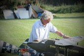
Hopefully, the problem with the inner engine exhausts has now been fixed. This picture shows the gap between the exhaust flexy pipe and the silencer stub; exhaust heat directly onto the silicon tube bridging the gap soon destroys it and if the flexy touches the tank, that too is melted. The simple solution was a short length of K&S thin-walled brass tubing, the silicon now forms a bit of a seal between the flexy pipe (which is slightly smaller than the silencer stub) and the brass tube but does not come into direct contact with the hot gasses. With there now being a metal bridge, there should be improved heat conduction. As an additional safety measure a piece of thin aluminium sheet has been glued under each tank. The 3rd flight was captured on video, still shaky in parts I’m afraid, but proves that the model has successfully flown again. The day was fine enough though a little choppy leading to the model being buffeted at times. The speed was kept slightly on the high side, I’m sure this can be reduced in better conditions to create a greater sense of realism but the greater aileron movement afforded by a one-servo-per-aileron installation showed that the model can now cope with a bit of turbulence. Resized, edited DH86 3rd flight.mp4 The little Lasers started easily and performed faultlessly, once again thanks to Jon Harper at Laser Engines for working his magic. From building three other deHavilland twins and multis, I’ve found there is a slight disadvantage (for the modeller) to their designs. The adoption of a single fin/rudder puts it out of the propwash. With the DH86 the outer engines are a considerable distance from the centreline, less than perfect engine synchronisation causes a tendency to swing on the take-off run which is difficult to correct with rudder alone. To counter this, each engine servo has its own channel with the outer engines slaved to the rudder. Full rudder output will advance the opposite outer engine by about 10%, ie right rudder will open the throttle of the left outer engine. The right outer engine in this example is not reduced by 10%; modern radios make this mixing very easy as Side A and Side B, in Futaba parlance, can be programmed independently. The cost of the restoration hasn’t been kept but it will have been a few hundred pounds, cheaper and quicker than starting from scratch I suppose. Cynically it could be described as mutton dressed as lamb, however I’m pleased with the final result and hope now that it has proved itself. it gets flown a bit more often than when first built. I’ll admit that it has been a more enjoyable project than I first thought, given that I reluctantly carry out repairs and this restoration was essentially just that. In building a model from scratch most are effectively prototypes as a subsequent one doesn’t usually get built to correct the inadequacies of the original, so a first for me on that score. This was the second of a two-model refurbishment I had tasked myself to do (the other was an equally old DB SE5) to prevent unairworthy models from taking up valuable space in my shed. In truth that was only buying a bit of time as now they are complete, I feel the need to tick off another attractive subject on an ever growing list. I’d better sweep out the workshop and worry how I’m going to squeeze another project into the shed.
-
Thanks for the compliments, its well appreciated. The little engines are bedding in nicely, even after only about 1/2 hours running, thanks to Jon Harper for getting them back to health. Here's a shaky bit of video, in my haste I had fitted a nearly flat battery into the camera instead of a charged one, so the camera cut out after a minute of so. The sound change when the exhaust blew can be heard as it comes overhead. Here's one more of Mike Mennell's photos from a different angle - now I really ought to get those homemade exhausts fixed so that flying can continue. 457295767_DH86PostRestoration1stFlight.mp4

