

Gary Manuel
-
Posts
4,897 -
Joined
-
Last visited
-
Days Won
10
Content Type
Profiles
Forums
Blogs
Gallery
Calendar
Downloads
Everything posted by Gary Manuel
-
That's it for today. Hope to post more pictures and maybe catch up to where I'm up to tomorrow. Edited By Gary Manuel on 08/04/2014 23:48:31 Edited By Gary Manuel on 08/04/2014 23:49:00
-
And another view There is space to add a 6mm facing to the front of the cowl, still leaving 3mm gap to the prop driver Edited By Gary Manuel on 08/04/2014 23:48:47
-
Cowl shape just about there. Still a bit more work to do on it but its taking shape.
-
Cowl partly made
-
Engine fitted back in to help with cowl measurements. Stringers in cowl slots. Accurately aligned by tacking with cyano.
-
The cowl will slide into the 3mm gap - like this.
-
Close up it looks like this
-
While the wings drying, lets do the cowl Triple laminated lite ply strips made up and glued to the engine box with a 3mm gap.
-
Leading edge trimmed and 12mm balsa strip added
-
When dry, a razer saw blade (without the handle) was used to separate the aeleron and flaps from the wing using the small gaps as a guide. Note that the end facing is already in place on the released control surfaces. The designer recommends using a band saw for this. I didn't for 2 reasons 1. I only have a scroll saw. 2. I'm not that brave Edited By Gary Manuel on 08/04/2014 23:34:31
-
Top trailing edge sheeted taped, clamped and weighted- again there is a 1mm or so gap between sheeting and rear spar. Edited By Gary Manuel on 08/04/2014 23:29:33
-
Note the extra short rib with a samll gap between the proper ring and the small pen mark on the sheet to mark the position of the gap between them. This gap, and the 1mm gap between the trailing edge sheeting and spar will later be used to guide a saw blade to form the aelerons and flaps. Edited By Gary Manuel on 08/04/2014 23:27:05
-
This is where I calculate that the wing bolts will be. Hopefully, the hole I drill will pass straight through the centre of these blocks
-
Just a bit more work on the wings. The odd looking trailing edge is sheeted, leaving a gap of 1mm or so between the sheet and the spruce spar.
-
The Hitec with the long arms will be for the rudder. The other one will be for the tow release (if I decide to use it as a tug).
-
Thought better of it and decided to go for full length pull-pull system with the servo mounted in the cabin. Edited By Gary Manuel on 08/04/2014 23:17:50
-
I did think about putting it here instead and having a long wire pull / pull rudder control
-
The designer recommends setting this servo box into the fuselage top here. The triangle behind is the tail fin strake. The idea is that the servo fits into the box, with the servo arms just clear of the tail. The strake is then just tacked on over the top of the servo arms, with a small slot cut into it to give clearance. Problem is that if you ever need to get to the servo, you need to take the strake off first. I don't like this.
-
cabin area cleaned up a bit. I will fill / sand the joins later.
-
The hatch tongue locates under the front and is held in by two magnets at the rear. I'll add a fake aerial or something to act as a handle later.
-
The centre section lifts out to give access to the engine servos and tank
-
OK - a few mor pictures. This is the front end after sheeting.
-
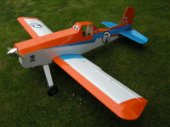
Well I would say that Kevin has got the wheel proportions about right, 5 to 5 1/2 inches I would say. What this model may lack in beauty, it makes up for in character I think - especially when I dress it up as Dusty.
-
KF - That's made my mind up. I have a set of 4 inch inflatable wheels on order, but I might be able to change it. Youre's looks about right I think. Iqon - Don't worry, it won't be the ugliest thing at my local club
-
Kevin, Looks good without the paper bag. What size wheels did you use? Edited By Gary Manuel on 08/04/2014 21:08:11
