Nigel R
-
Posts
6,994 -
Joined
-
Last visited
-
Days Won
3
Content Type
Profiles
Forums
Blogs
Gallery
Calendar
Downloads
Everything posted by Nigel R
-

Are we putting too much balsa into models?
Nigel R replied to kc's topic in Building from Traditional Kits and Plans
Ugly stik was originally designed in times of doped silk? This provides a hefty dose of resistance to twist, when finished. Shrink film plastic, less so. But if you want to build open frame wings, go ahead. They'll simply be less strong than fully sheeted. Ps gliders guys are probably interested in accuracy of wing section and would probably prefer a fully sheeted wing of some description...? -
Here I've sheeted the tailplane. This is a closeup of the trailing edge of the tip of the tailplane, along the hinge line with the elevator. You can see the snake now embedded in the structure. The snake emerges into this rectangular pocket (which I haven't sheeted, for reasons). The clevis will live inside the pocket, as will the rudder horn. Hopefully this will be better illustrated a bit later on. The sheeting over the pocket is done using a 1/32 ply insert. I figured that would give me just a touch more space inside the pocket. This shot is from the sheeted side of the above structure, with the ply insert on the bench. More soon.
-
This is the tailplane internal structure. It will be sheeted with 1/16 later on. The quarter circle I carved out to accept the snake is (I hope) obvious 🙂 At the tip of the tailplane, toward the rear of the structure, is the pocket I am building to hide the rudder horn. More on that soon.
-
I've now taken the plunge, doubled my mortgage, and ordered some balsa from SLEC, as I'm reasonably certain of most of my construction details - given that I've already made a very similarly sized twin with the same fuselage shape / nacelles. However, I have already started some work on the model using some wood I had "spare". I figured I would try and work the part of the model that I was least sure about - which at this point is the twin tails. Wishlist: * Two independent rudders on two servos * Able to move a full 45 degrees for useful airbrake function * No weak control links * No messy external hardware I figured I had a few options for controlling the rudders: * Something with bellcranks and pushrods * Snakes of some sort * Closed loop being routed, somehow, from fuselage through the tailplane itself then on to the rudder * a torque rod, going from inside the fuselage, to right out near the rudder, with a short link rod to the rudder itself. * burying some servos in a tailplane or fin I ruled out bellcranks quite quickly, although they'd probably be functionally ok, they were quite large and I'd not be able to hide them inside the structure. The structure would need to be quite deep - much deeper than I'd hoped. I made a test piece with closed loop, but I wasn't very happy with the very tight curves I found were needed in the guide tubes. I very nearly used torque rods - I got as far as making a pair of double ended rods up from 3/32. This was promising, but, after making them I tested how rigid the rod was, and with the (quite long) lengths involved, I found they were too flexible for my liking. I didn't want any issues with flutter in flight, or for the torque rods to be too weak to sustain a knife edge type situation. I ruled out using individual servos - the really flat servos are too pricey for me. This pretty much only left snakes. To check viability of these, I worked out what the largest, shallowest curve I could use whilst still containing one snake in each half of the tailplane. Short version, this appeared to be viable. And I also figured, if I was a touch crafty and with some careful building, I could also hide the rudder horns safely inside the tailplane structure. I'll put up some pictures soon - they'll explain more than my words have!
-
Flew her for a second time yesterday. Aside from a blown OS#8 plug (argh! £££!) and the loss of an M4 exhaust header bolt during flight, it was all good. She definitely needs a little CG adjustment but a promising airframe for sure. Quite docile near stall with current CG, yet the spin is lovely and flat on rudder/elevator alone. The only fly in the ointment, so to speak, is down to how sleek she is - she is fast, the glide slope is quite flat, and slowing her down on finals takes up a fair amount of sky - she could really use something (flaps or breaks or whatever) to dirty up the airframe a bit. Maybe I've just forgotten what "proper" classic pattern airframes are like! It's no particular big deal at the field I'm flying these days at but it would be very tight on a short strip.
-
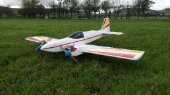
Challenger has finally flown! Very smooth maiden with no problems. Really pleased. OS performed flawlessly and provides endless vertical. The pipe length is set about right, although i need a longer header than the current one. Rolls are axial, loops smooth, snaps are sharp and precise. I still need to trim the cg, it is a little forward. I also have some adjustment to do in the throttle to get a slower idle, but, all things considered, I am a happy chappie. It also looks pretty darn good in knife edge. Photos were taken after returning to terror firmer.
-
Overlander use rebadged Hobbywing. Or at least they have done historically. Just FYI.
-
Some more background. I've built several twins. The first was a conventional layout (build log - Double Trouble) and the second was a double fuselage layout (build log - Doppleganger). The twin fuselage is the one with the rudder airbrakes. Aesthetically, I was quite pleased with the fuselage shape on Double Trouble... ...so I'm going to base Orthus on Double Trouble. Not a rehash mind, more an evolution. Double Trouble had a constant chord wing and was very mild mannered. This time around, being happier with twins in general, I'm going to use a slightly spicier tapered wing for better aerobatics. I found the overall size of the airframe made transport easy enough (62" span) with a single piece wing. Obviously it will look a bit different with the twin fins. As an aside, I was very tempted to do a kit bash from the Galaxy Warlock... ...but, it's a big bigger than I wanted, it is 74" span.
-
RCG can be very "anti". I guess at around ten minutes a pop, that's 800 minutes of air time, (round up) call it 15 hours of stick time. Doesn't seem unreasonable to learn enough skill to consistently pilot something to B standard. .
-
Anyone know what make this is and if it is worth anything?
Nigel R replied to Arthur Harris's topic in IC Engines
Definitely not Vega, they were all machined from solid (IIRC) and looked very, very different. What are those bits on the back of cam box? Something to do with adjusting the cam timing? My other bet is that the odd bits are a gear fuel pump - the other photos seem to show a fuel nipple on the far side of it. -
My flight log is one page of a larger spreadsheet where I also work out motor setups and record a bunch of other "useful info" like servo torque and fuel cost and lipo cost and some of that can then get used to work out cost per flight of each airframe, and so on. I also do some rough figuring out of build times and build costs in other tabs.
-
Yes. Takes but mere moments after a session... Helps figure out what I'm actually really getting value from. Amongst other things.
-
The mythical Orthus had several distinguishing features; for starters he clearly had two heads. But he was also depicted with a tail that had a sting like a scorpion or even a snakes head on the end of the tail. A bit of a beast. Orthus is a project I've had on my wishlist for a while. What will my Orthus be? Orthus will be a twin engined airframe - like his mythical counterpart with two heads. I'm currently undecided between using a pair of Irvine 39, OS 46 SF, or OS 56alpha. But what to do about his other feature, the tail that ends with a sting? Something different is called for. Here I decided a little while back that I would have a go at making this airframe with a 'tail end feature' - twin fins. Why twin fins? Simple - I have had good experience on another project with twin fins providing an airbrake option, by pulling both rudders inboard by 45 deg, allowing for a steeper descent into shorter strips. It's like having a parachute hung out the back. Most airframes would use flaps for a similar function; twin rudders provide an alternative option.
-
Orthus Mythical two headed dog. The brother of Cerberus; the guard dog of the Cyclops. More soon...
-
Doesn't look very red. Must be fake.
-
And what will you do with this information? Learn to walk before running, etc.
-
Yes, no, maybe. Depends on the particular nature of the job. Some actively prefer a somewhat lower social media profile.
-
We value your privacy pop-up on every page!!
Nigel R replied to Christopher Long 1's topic in Report A Problem
All the thread reply buttons have ceased working for me, if I used Chrome on my PC. As have anything like "edit" or the reaction buttons, or quote - all gone. The same is true on my mobile using the phone's browser. I'm on a different pc for now, using the microsoft browser, but, I can't use that on my main PC, so I'm effectively now unable to post... -
Cut hole in fuselage behind lipo, job done. For added bling, use a scoop over the hole, but backwards, so it sticks air out
-
Generally true C8. Back-EMF increases with rpm (i.e. with more power, for us). Given that the FETs are switching directly on to a coil, this may mean voltage spikes/peaks/noise during switching have different effects at different speeds and loads. Worth noting, our brushless motors are not a switch mode power supply though, and work differently (although both involve fast switching). That said I am far from an expert - this thread could use one...
-
It's all straight lines. If I remember right, the solid side has a perfectly straight line right from the front to the rear. If you make sure your sheet of wood has a straight edge, you can "just" measure off from that straight edge as a reference line. Then cut the second one using the first as template.
-
A thought, the remote needle can be mounted literally anywhere. Perhaps a different bracket could be made from metal (recycled baked bean tin) or a printed bracket / holder / adaptor?
-
Overlander use rebadged Hobbywing don't they? Last I checked they were generally ok. I would stick the ESC out in the breeze for now. Simple, effective - this is a trainer, not a concourse d'elegance winner. If you want to use the scoop (which looks very neat) I'd use it as an air exit, just behind the lipo and on the underside of the fuselage. That would then draw air, and very effectively too, through the model - over all the electronics.
-
Must admit the engine mount is one bit i can't see the advantage of printing. What will it get you over one of the usual commercial nylon beam mounts?
-
Seems like it's an easy fix to repair the bust elevator. I wouldn't be writing off that 400 just yet.