Alan Gorham_
-
Posts
1,950 -
Joined
-
Last visited
-
Days Won
2
Content Type
Profiles
Forums
Blogs
Gallery
Calendar
Downloads
Everything posted by Alan Gorham_
-
Limbo Dancer Alternatives
Alan Gorham_ replied to Nigel Heather's topic in General Electric Flight Chat
It's not easy to do that due to the bulk of the Lipo pack and the confined area where it can fit in the fuselage. It is however possible to place the Rx pack under the rudder and elevator servos. It lives there on my Limbo... -
The first 3 4-strokes that OS sold commercially were the open rocker 60 and 75 and then an enclosed rocker 80 (still with the cam gear to the rear of the cylinder). The 90 followed those 3 in around 1984 and was definitely fitted with a rocker box.
-
Fairly sure Chris is a member of this forum. If you search his name you will be able to find his account and message him for details. His model certainly looked the part and flew nicely once trimmed.
-
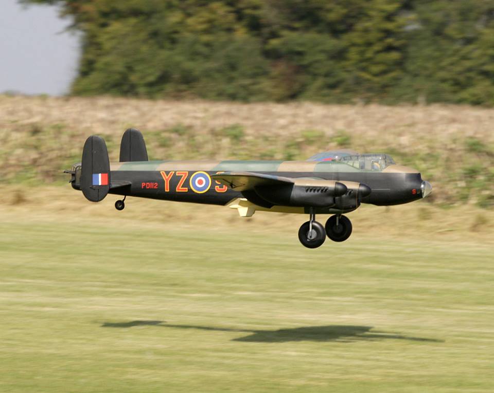
It's already been done, so the answer must be yes! This was the maiden of a plan built model last weekend at the PSSA meeting on the Great Orme. The model was built by Chris Collis to an enlarged plan designed by Paul Sampson. VID-20221009-WA0002.mp4
-
Let's hope it doesn't crash the model or burst into flames...
-
This is what I think a genuine S3003 looks like. You can see the difference in shape.
-
Pete those 2 servos in the Fuselage don't look like genuine Futaba S3003s to me. The shape and features on the case are wrong and the grommets are different to the genuine Futaba types. It's hard to tell but it also looks like you might have installed the brass ferrules into the grommets the wrong way up. The flared out end should be in contact with the top of the ply plate, not the mounting screw head.
-
Nothing to be lost by quickly checking the tappet gaps?
-
Peter Rake 36” Sopwith pup conversion setup
Alan Gorham_ replied to Hunter's topic in Power System Selection
Just for interest I am a fan of Peter Rake's designs. Here is his Isaacs Fury that I built the prototype of and his Sopwith Camel that I have in build. -
Peter Rake 36” Sopwith pup conversion setup
Alan Gorham_ replied to Hunter's topic in Power System Selection
But there are multiple ways to achieve a usable result in electric flight. One person's shopping list is not the definitive list. Imagine if 10 people give the OP a completely different list. That would be unusable and confusing so perhaps some knowledge may be able to allow the OP to make a more informed decision themselves. Of course the easy answer is just to recommend ringing George at 4-max and ask him to put together a complete power system which he is happy to do as many members of this forum have done successfully in the past. -
Peter Rake 36” Sopwith pup conversion setup
Alan Gorham_ replied to Hunter's topic in Power System Selection
Instead of just giving you a shopping list maybe a short explanation of the theory will enable you to understand how to size power systems? It's irrelevant whether they are brushed motors or brushless by the way so there is no need to be baffled. If we consider the old brushed power system that used a Speed 400 with 2.33:1 gearbox. I will assume that you used an 8 cell Nickel based battery and something like a 9 x 6 prop. Graupners Speed 400 7.2V variant has a kV figure of 1762 revs per volt. Assuming the old 8 cell pack maintained a terminal voltage of 9.2V at full throttle, that means the motor turns at 16210rpm, ignoring slip. The 2.33:1 gear ratio means the prop will turn at 6957rpm. Using an online pitch speed calculator gives a full throttle flying speed of 47mph, ignoring drag etc. That all sounds in the ballpark for a WW1 biplane. The recommended maximum current for a Speed 400 motor was around 9A so to see how much power was used to fly the model using the above system we do 9.2 x 9 = 82W. Peter Rake designs commonly end up around 20oz AUW, so the power loading in the brushed case was 65W per lb. If you wanted to use a 2S Lipo and keep the same size prop, then you could go for a brushless motor capable of more than 82W and a kV rating that will turn the prop at a near equivalent speed to the geared 400. There are lots of around 100W outrunner motors with a kV of 1000 that will do the job. As an example look at 2212 size motors with the 1000kV rating. -
Peter Rake 36” Sopwith pup conversion setup
Alan Gorham_ replied to Hunter's topic in Power System Selection
That setup is way way too much for a 3 foot Peter Rake bipe. It's in no way equivalent to a geared Speed 400 setup. You only need around 80W to fly your model, not 350 to 400. -
F4C and F4H World Championships Norway
Alan Gorham_ replied to Maurice Dyer's topic in Scale Matters
.... -
I thought the advice was to land immediately if something falls off in flight?
-
Diesel engine, could use some help.
Alan Gorham_ replied to Jeffrey Cottrell 2's topic in All Things Model Flying
I found with mine that it was a ready starter if you give a tiny prime (2 or 3 drops only) against the side of the piston with the exhaust ports closed. I'd make my own tank from sheet tinplate and brass tube as sold by K&S. -
Diesel engine, could use some help.
Alan Gorham_ replied to Jeffrey Cottrell 2's topic in All Things Model Flying
It's an AE engine, not an AM. Both designed by Dennis Allen but the AE designs were made in the early 1990s. -
Rans S9 Chaos- Flying Characteristics.
Alan Gorham_ replied to Mr Ficky's topic in Peter Miller plan builders
The Zlin Z50L has 3 degrees sidethrust according to the old MAP scale drawing. -
If the model is built correctly and all the surfaces and systems have passed a pre-flight check then I fly. I generally don't taxi my models to and from the runway for safety reasons so a taxi test would tell me nothing. Again, a test hop to me seems counter-productive. More likely to end up with the model running out of runway and ramming the scenery. They were built to fly!
-
What plane is this??
Alan Gorham_ replied to Sven Yonson's topic in Vintage Kits, Semi-Kits and Plan Projects
I have a nose for aeroplanes! If the builder had stuck to the plan it would have been easy to identify as the Spook is a very distinctive shape. But we got there in the end! -
What plane is this??
Alan Gorham_ replied to Sven Yonson's topic in Vintage Kits, Semi-Kits and Plan Projects
Jim, nice to hear from you. Yes if you compare fuselage and tail shapes they are the same. Since no vintage models had ailerons I am saying that the builder of the model in the OP has modified the wing to have straight dihedral and ailerons. Sacrelige! -
What plane is this??
Alan Gorham_ replied to Sven Yonson's topic in Vintage Kits, Semi-Kits and Plan Projects
It's a Spook, but it's hard to identify because the builder has straightened out the gull type polyhedral and fitted ailerons. -
Legal Drone Flyer Threatened with Gun
Alan Gorham_ replied to EvilC57's topic in All Things Model Flying
Just in the interests of accuracy, let's see what the first three posts on the Gatwick drone thread said.... -
E-flite units have a long history of one of the control units giving up on many forums with international contributors. Not sure I'd use them with confidence based on the reports.
-
Note that only the speed controller, charger and NiCd are Futaba. The radio is a Reftec item. As far as I'm aware Futaba never offered UHF radios.
-
I'd love to know how the OP would be able to follow those instructions bearing in mind he can't read the LCD display on his transmitter...