Mike T Posted December 31, 2017 Share Posted December 31, 2017 Before you go any further with the fuselage, I'd urge you to cover the butt joints with a 1/16" ply doubler, generously overlapped. Feather off the edges and slim down the rear former to suit and it will be barely noticeable, but add a lot of strength to a built-in weak spot. CF uses the same fus. jointing method on his MPII as he does on the Phase 6 - where it is a notorious weak point (to the extent that his revised instructions for the 6 now advise you to double the joint. I did as per instructions and it still failed...) Bear in mind that if you are going to use dowels and wing bands, then the rear dowel will be going right through this area! Re ballast - don't bother with a box. I fitted a thick liteply plate to the fus bottom, chamfered to sit over the triangular longerons and about 60mm long. A 6mm bolt projects up though this at the CG position and pieces of lead flashing fit over it, secured with a wing nut. Note that the substantial cross-sections of the longerons and the thick top and bottom sheeting allow you to be quite aggressive when rounding off the fuselage - nothing worse than a MP (or a 6) with just the corners knocked off! Quote Link to comment Share on other sites More sharing options...
Jonathan M Posted January 1, 2018 Author Share Posted January 1, 2018 Mike, I assume you mean the 1/16" doublers on the inside of the fuselage sides? If so, these are provided and now glued in place. I'l be using 5mm nylon bolts and captive nuts to secure the wing (and smaller ones on for the tailplane) so am ignoring the dowels provided for rubber-bands. Will also ignore that 'micro-mould' rear wing-fixing bracket and just make up a suitable piece of hardwood to hold a captive-nut. Good idea about an up-sticking 6mm bolt to secure ballast. I have a lifetime supply of roofing-lead offcuts, which can be neatly trimmed into unit sizes (say 2oz each) to snugly fit. Absolutely agree about properly rounding the corners! Quote Link to comment Share on other sites More sharing options...
Jonathan M Posted January 1, 2018 Author Share Posted January 1, 2018 A bit more progress today. The tapered nose cappings were glued on Aliphatic (which I'm 'sticking' to for most of the wood joints). And the spruce spacer to hold the elevator snake at the rear. The white snakes are those supplied in the kit, but I'm using Sullivan Snake 'N Rod kit instead. Also treating the MP to nicer control horns (R) than those supplied (L). Nothing wrong I'm sure with the kit-supplied stuff (certainly as far as my flying skills are concerned!), just that "a little bit of what you fancy is good for you". Shaped the underside of the spruce bit at the rear to match the ply profile. Then glued on the spruce capping piece to the front of rear 'decking' - as this where the TE of the wing meets and needs robustness. Finally, mixed a bit of 5-minute epoxy and got one side of Former 7 in place... ... while the remainder of the epoxy got the end of the snake down on the rear spacer. Tomorrow hopefully will see the fuselage assume a three-dimensional form! Jon Quote Link to comment Share on other sites More sharing options...
Andy Blackburn Posted January 2, 2018 Share Posted January 2, 2018 Looking good. I now remember why Cris Foss kits are so rewarding to build. A. Quote Link to comment Share on other sites More sharing options...
Mike T Posted January 2, 2018 Share Posted January 2, 2018 Yes, Jonathan, those are the plates! Glad to see this issue is addressed by CF! TBH, I think the Micro-mold brackets are quite a good way of providing a bolt anchor point. They have a bit of give, which should survive the odd 'skewed' arrival. That said, it's hard to beat the simplicity of a bit of 1/4 ply with a captive nut, glued under the wing seat longerons. Re horns, I find most of the commercial stuff a bit clumsy and never quite right for their intended application, so usually make my own from fibreglass sheet, or squashed brass tube. Andy is quite right about CF's kits - there's nothing like building in wood... Quote Link to comment Share on other sites More sharing options...
Martyn K Posted January 2, 2018 Share Posted January 2, 2018 Looking good. Following.. Regarding colours. I find all black models very difficult to orientate correctly. I would put some broad white stripes underneath to give it/you something to distinguish between top and bottom and perhaps add some pink at the upper wingtips Good luck Martyn Quote Link to comment Share on other sites More sharing options...
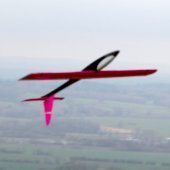
Jonathan M Posted January 2, 2018 Author Share Posted January 2, 2018 Cheers Guys Mike, I had a brief look online for the micro-mold brackets, but couldn't find any so will have to make my own anyway. Martyn, you're right about all black models. But if you look at my sketch, I've got fat shocking pink lettering right across the top of the wing, and broad wonky white stripes in the middle of the underside of each wing and the tailplane. The fin and rudder will be changed to pink with black for the numeral, and the underwing striped widened. Quote Link to comment Share on other sites More sharing options...
Jonathan M Posted January 2, 2018 Author Share Posted January 2, 2018 In the meantime, I'm a little bit stumped about the wing-tips. Both the original non-aileron and aileron wings had wing-tips made from supplied 3/4" stock, as per the instruction sheet. But the both wing sets supplied (I have both, having originally bought the 2-chan trainer version then ordered the aileron wing set as I'd already started slope flying with a foam aileron model) contain only a simple 1/16th ply capping piece and no 3/4" balsa. The question is how will these thin ply cappings work with the ailerons?! They'd be fine with the non-aileron wings of course, but I can't see how they'd work with the ailerons butting right up to them?! Maybe the slip of paper for the new 'improved' aileron wing was omitted from the box? My options are to either glue a length of TE stock (cut from the ailerons) onto the last 3/4" towards the tips then flush to the angle and cover with the ply supplied, or make up my own 'original-style' wing tips by laminating three pieces cut from 1/4" balsa in my stocks - but the latter will increase the wingspan slightly, so I'll probably go for the first option. Quote Link to comment Share on other sites More sharing options...
Jonathan M Posted January 2, 2018 Author Share Posted January 2, 2018 All the while, the rear decking for the fuselage is drying on one side... And I've made a start on the aileron servo pockets by boring 6mm holes in the corners and gluing in 18mm long dowelling-studs (roughly 22mm depth available, less 1.5mm thickness of plastic servo-cover, less safety-margin). When these are dry, I'll start the twin archaeological digs, with the aim of removing only as much foam as necessary to give the servos and leads room to bed-down. Quote Link to comment Share on other sites More sharing options...
Andy Blackburn Posted January 2, 2018 Share Posted January 2, 2018 > The question is how will these thin ply cappings work with the ailerons?! They'd be fine with the non-aileron wings of course, but I can't see how they'd work with the ailerons butting right up to them?! I think you'd normally cover the tips and ailerons with ply capping, then cut the ailerons free so that the tips and ailerons both line up? If that makes sense? But I think either way would be fine, actually. There's very little you can do to it to make it not fly properly... A. P.S. - v impressed with the dowelling... Edited By Andy Blackburn on 02/01/2018 19:15:38 Quote Link to comment Share on other sites More sharing options...
Jonathan M Posted January 2, 2018 Author Share Posted January 2, 2018 Posted by Andy Blackburn on 02/01/2018 19:14:44: > The question is how will these thin ply cappings work with the ailerons?! They'd be fine with the non-aileron wings of course, but I can't see how they'd work with the ailerons butting right up to them?! I think you'd normally cover the tips and ailerons with ply capping, then cut the ailerons free so that the tips and ailerons both line up? If that makes sense? But I think either way would be fine, actually. There's very little you can do to it to make it not fly properly... A. Yes, that makes sense, but I'll still want 3/4" of fixed trailing edge between the aileron and caping strip, whatever method I use to achieve it. Jon PS There's much I can do to make it not fly properly... just wait till I get on the sticks! Quote Link to comment Share on other sites More sharing options...
Jonathan M Posted January 2, 2018 Author Share Posted January 2, 2018 Pockets de-skinned (but if it was a fish then just 'skinned' I suppose!). Dowels needed a tad more PVA to fill the odd gap in the foam. Tomorrow we dig. And the other side of fuselage glued on. Tomorrow - hopefully - the whole thing will pull together on all the formers, the nose-block added, and balsa glued cross-grained to the undersides. I wonder whether its worth securing the snakes mid-way between the tail and where they emerge through the hole in the former at the TE of the wing to reduce the likelihood of slop? Edited By Jonathan M on 02/01/2018 22:35:19 Quote Link to comment Share on other sites More sharing options...
PatMc Posted January 2, 2018 Share Posted January 2, 2018 Posted by Jonathan M on 02/01/2018 21:55:12: I wonder whether its worth securing the snakes mid-way between the tail and where they emerge through the hole in the former at the TE of the wing to reduce the likelihood of slop? So long as the snakes are held securely at both ends, support in between will have no effect on the slop. Edited By PatMc on 03/01/2018 00:00:01 Quote Link to comment Share on other sites More sharing options...
Jonathan M Posted January 3, 2018 Author Share Posted January 3, 2018 Cheers for that Pat. The way it all goes together means that there's no way to do this once the rear fuse is sheeted. Quote Link to comment Share on other sites More sharing options...
Mike T Posted January 3, 2018 Share Posted January 3, 2018 Typical aeromodeller - loads of planes... I think the wingtips are a bit of a cop-out from CF. At least he could have put in some thicker stock so you could get some sort of a profile! I'd go with laminated 1/4 sheet - preferably with some 1mm or 1/16 ply in the sandwich to reinforce the edge. PS - like the dowels too. Gonna nick that for my next one! Edited By Mike T on 03/01/2018 13:09:10 Quote Link to comment Share on other sites More sharing options...
Jonathan M Posted January 3, 2018 Author Share Posted January 3, 2018 Posted by Mike T on 03/01/2018 13:07:24: I'd go with laminated 1/4 sheet - preferably with some 1mm or 1/16 ply in the sandwich to reinforce the edge. Good solution that! Will laminate three slices of 1/4" with two fillings of 1/32" ply, then bond straight onto the exposed foam. Re dihedral, CF suggest 1" dihedral if the MP is to be used as an 'aileron trainer' or flat wing for 'experienced fliers'. I'm sure I'll be fine flying with the flat wing, but might let in a very slight 1/2" dihedral...? Quote Link to comment Share on other sites More sharing options...
PatMc Posted January 3, 2018 Share Posted January 3, 2018 Nice build Jonathan. A couple of suggestions - a) If you haven't joined the wings yet, instead of running the servo extn wires behind the LE it's quite easy to make a hole from the root to the servo pocket directly through the foam. Stand a wing half vetrically on it's tip well supported to stay steady, place a piece of scrap ply on the tip side of the pocket. Get a straight piece of thick wire (I used something like 1/4" piano wire) at least about 3" longer than the distance from root to pocket. Hold the top end of the wire with pliers over about 5" or 6"the spot that the hole's to made from. Heat the bottom tip of the wire with a gas blow torch just enough that it will melt into the foam when in contact. Then carefully lower it into the foam allowing it to melt it's way through until it reaches the pocket, then withdraw the wire. It's one of those jobs that's easier to do than explain. I've done it on several glider wings up to 9ft span without mishap, just takes a little bit of forethought & preparation. It is easier if you can get someone to hold the blow torch, last time I did it I got my wife on torch duty & I held the wire with oven gloves. She complained like hell afterwards that I hadn't warned her about the fumes b) Make provision to mount the ballast externally held by a screw(s) into a T nut(s) on a ply base glued to the inside of the fuselage floor. A cast lead weight is neatest but a strip or more of lead mounted like a skid would be just as effective. The big advantage over internal ballast is the ability to fit or remove it without hassle on a cold & windy slope site. This is a 300g chunk of lead cast in damp sand. I used an ornamental pottery egg to make the impression. I made this many years ago as a ballast for an OD sloper about the same size as the MP, the white stuff is remains of some caulk material used to make it a close fit to the fuselage bottom. Quote Link to comment Share on other sites More sharing options...
Jonathan M Posted January 4, 2018 Author Share Posted January 4, 2018 Cheers Pat - and for both suggestions. The hot wire method seems easy enough, and gives the option of pulling damaged wiring out etc, but I don't have a blowtorch or gas hob. The alternative of running the extension lead forward (drill through a short length from the LE) then along it (score a groove into the foam) before gluing on the balsa is also easy enough. I'll mull on the alternative solution for ballast. Outside avoids the (relatively minor) faff of unscrewing the wings, but inside doesn't spoil the lines. Quote Link to comment Share on other sites More sharing options...
Jonathan M Posted January 4, 2018 Author Share Posted January 4, 2018 Inching onwards. Remaining formers in place and brought the nose together. Been using 5-minute epoxy for these jobs, which should be strong enough, and 3M tape to bind until dry. The two tail bones weren't perfectly aligned, so a smear of epoxy did the job. A minor bit of shaving and sanding to ensure the profile of the two halves were properly co-incident and the lines fair before I start cutting and gluing on the underside sheeting. And similar for the top decking before starting the rounding-off to section. Edited By Jonathan M on 04/01/2018 07:33:07 Quote Link to comment Share on other sites More sharing options...
Jonathan M Posted January 4, 2018 Author Share Posted January 4, 2018 Yesterday not a hugely productive day (some work stuff intruded, had to go food shopping, and the kid is ill with a persistent flu), but while the fuselage stuff was drying did some digging out of the wing aileron pockets. The servos are an excellent fit into the inside slots of the covers, with very little slop, but I'll add servo-tape (or double-sided tape) on final installation to firm things up completely. Edited By Jonathan M on 04/01/2018 07:38:32 Quote Link to comment Share on other sites More sharing options...
Jonathan M Posted January 4, 2018 Author Share Posted January 4, 2018 With the hardwood nose-block planed and sanded down to shape, the under-fuselage sheeting could go on. Despite being ultra careful to waste no more than a postage-stamp's worth (literally!), there simply wasn't quite enough 1/8" supplied to allow for the last two narrowest panels. Luckily I had some suitable 1/8 sheet lying around anyway, but the kit should really contain enough of the basics for the job! Never quite trusting pins to hold things down properly, I've become a fan of using strong masking-tape to give a tight and comprehensive pull. Also trying SuperAliphatic for the first time, and liking it. I'm guessing that its strong enough. Edited By Jonathan M on 04/01/2018 20:04:21 Quote Link to comment Share on other sites More sharing options...
Jonathan M Posted January 4, 2018 Author Share Posted January 4, 2018 It strikes me that I am perhaps being a bit too detailed in documenting almost every step of this build? That said, as a first-timer to building from an RC kit and researching other builds before I started, I couldn't find this sort of detail in the few MP threads around, so I hope that this blog will be of use to others in a similar position. Jon Quote Link to comment Share on other sites More sharing options...
Richard Ashworth Posted January 4, 2018 Share Posted January 4, 2018 Hi Jon Please continue in the same vein. As a teenager 50 years ago I built from plan but much "simpler" planes, free flight and control line, nothing as exotic as foam wings with servos. I have the Middle phase on the possibles list and for me, your build thread has so far been brilliant for education purposes, both general build techniques and Middle Phase in particular. Regards Richard Quote Link to comment Share on other sites More sharing options...
Jonathan M Posted January 5, 2018 Author Share Posted January 5, 2018 Glad to hear that Richard! To be more explicit - I have built a number of small indoor free flight scale models from kits and plans, all stick-and-tissue, and done the RC installations on a couple of high-tech carbon DLGs as well as my ARTF Acro Wot, but the Middle Phase is my first build of a complete RC airframe of this sort. Jon Quote Link to comment Share on other sites More sharing options...
Wihtgar Posted January 5, 2018 Share Posted January 5, 2018 I'm in the same position as Richard, except I have a Middle Phase kit on top of the wardrobe ready to go! Keep up the postings, I'm finding them very informative, the last model I built was a La Mouette from a free Aeromodeller plan circa 1960's Nige Quote Link to comment Share on other sites More sharing options...

Recommended Posts
Join the conversation
You can post now and register later. If you have an account, sign in now to post with your account.
Note: Your post will require moderator approval before it will be visible.