Jonathan M Posted March 2, 2018 Author Share Posted March 2, 2018 Snow enabled play... Joiner slots hacked out, and bottoms masking-taped to prevent (five-minute) epoxy absconding: Joiners flushed off, extra margin taped off, whole area coated with two layers of sanding-sealer to prevent Poly-C moisture from penetrating veneer, and hole cut in bandage for servo-leads: First of four coats of Poly-C: Next up is making seats etc for wing-bolts and getting everything nicely mated... then onto shaping the fuselage! Quote Link to comment Share on other sites More sharing options...
Jonathan M Posted March 3, 2018 Author Share Posted March 3, 2018 Epoxied in the ballast bolt, and made 3mm ply bridges for the captive nuts. Tightening up the nylon bolts with the wing in place so the ply would seat snugly under the top longerons before the 5-min epoxy went off resulted in some creaking sounds... when I later took the wing off I discovered the cause of the creaking: I now have arched bridges! On the basis that it is the nylon bolts that are supposed to shear on an unplanned impact rather than the ply bridges fail and rip out, I really ought to laminate on (curved) strengthening beams under each one. With wing still snugly tightened in place, a straight-edge on the rear decking revealed that one side was several mm higher than the other: Also the wing seat needed shaping to match the wing section each side, so a bit of scribing (0.7mm deeper on the high side) and some gentle work with a miniature spokeshave dealt with that. There's still a bit of a gap near the LE, but I'll worry about tidying that up later with a fillet. The LE needed a bevel cut to match the slope on the rear of the hatch (which is all in the instructions): And glued the curved ply piece in place. I particularly like this photo because it finally shows that I've actually been making a glider rather than abstract sculpture! I've decided to revert to the shorter 6" hatch exactly as per the instructions (rather than the 7" version I considered earlier) and made the down-cut with a razor-saw while the section was still square as it seemed more accurate to do it that way. Tomorrow, after I've shaped the whole fuselage, I'll make the horizontal cut each side and fashion the hatch locating-tabs. Edited By Jonathan M on 03/03/2018 20:09:49 Quote Link to comment Share on other sites More sharing options...
Jonathan M Posted March 3, 2018 Author Share Posted March 3, 2018 Whilst waiting for things to dry, I also donned nitrile gloves and hacked some of my stash of roofing-lead into four leaves of ballast, each weighing 2oz. Just in case the ballast needs positioning a bit forward or aft of the designed CG, I made a slot in the middle of each leaf. And because lead isn't apparently very good for you, I wrapped each leaf in insulation-tape, after which I binned the nitrile gloves and made a cup of tea! This piccie of one leaf of ballast in place is quite useful, as it shows my 'architect-designed' arched bridges: More later... Quote Link to comment Share on other sites More sharing options...
Jonathan M Posted March 4, 2018 Author Share Posted March 4, 2018 This morning's work... First rough your fish: Then de-scale: It seems to look alright from this end: And seems okay from this end too: Slipped fin into the slot I made earlier and bolted wings on again (because I can!): Fuselage looks as shapely and symmetrical as it needs to be... while the black Oracover will I'm sure cover the multitude of small sins! Quote Link to comment Share on other sites More sharing options...
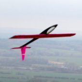
Jonathan M Posted March 4, 2018 Author Share Posted March 4, 2018 Just a hint of what I hope to being doing with my MP.... eventually! Quote Link to comment Share on other sites More sharing options...
Trevor Posted March 4, 2018 Share Posted March 4, 2018 Looking good! Maiden flight this month? Trevor Quote Link to comment Share on other sites More sharing options...
Jonathan M Posted March 4, 2018 Author Share Posted March 4, 2018 Cheers Trevor A March maiden certainly feasible... Quote Link to comment Share on other sites More sharing options...
Jonathan M Posted March 5, 2018 Author Share Posted March 5, 2018 So hatch carefully sliced off both sides: Then turned my attention to the compromised and creaking arched-bridges - a sharp downwards tap with a small hammer took them neatly out! Then found some proper ply (4mm birch which is much more robust and has plies of equal thicknesses) and fashioned new bridges: Once the new bridges were glued in dry, added some softwood braces above on which the wing now virtually sits: Next up was to prepare a weapon of long rotation: This extends past the battery bay to bore holes through its forward bulkhead into the nose-weight cuddy: And another weapon... ... to sort of square off the rough hole! When the right amount of lead has been found by trial and error, the hole can be sealed with a thin ply plate and held in place with the battery wrapped up in foam. And then the moment which fills me with joy that I've passed the half-way mark on the whole build - planning the fuselage servo installation: I did think about mounting these smaller than standard servos a bit further forward to help reduce the amount of eventual nose-lead, but there's probably very little in it - and it seems a good idea to glue the aft bearer to the bulkhead as directed in the instructions, and not reducing the robustness of the whole assembly in the event of a bumpy landing: I meant to glue the the littlle locating-tabs on the severed canopy, but there's always tomorrow... and the day after that.... and the.... Quote Link to comment Share on other sites More sharing options...
Jonathan M Posted March 16, 2018 Author Share Posted March 16, 2018 Rails and servos installed. Briefly connected up the battery and RX to make sure the servo arms were aligned on ther splines for a perpendicular angle at zero trim, then cut off the redundant bits: Hatch locating tabs glued on and checked fit: First go at trimming wing-fuselage fairing - which fouled nylon bolt head: Second pass with the scissors cleared bolt - but by the time I'd finished trying to get a good fit around the leading-edge and fair with the hatch the plastic had shrunk too much! There's a spare fairing from the original RE wing in the kit, so I'll have a fresh go later.... Quote Link to comment Share on other sites More sharing options...
Jonathan M Posted March 16, 2018 Author Share Posted March 16, 2018 So much for the top, now for the tail. The 'structions suggest either a banded-on tailplane or a screwed-on one, but I decided to use 2mm nylon bolts for rigidity plus safety. The problem then arose of not being able to get the captive bolts in from the underside, so I decided to recess them in from the top (having slimmed down the rear one to clear the sides), CA'd them in and then glued the 1/16" ply plate on top - captive enough: The rudder snake sheathing was then installed - a low angle hole was (messily) bored then opened up with a round file; with the snake glued in, dry and flushed off, a bit of scrap balsa was let in to fair over the mess on top, which will all be 'perfect' once the thing is covered: Quote Link to comment Share on other sites More sharing options...
Jonathan M Posted March 16, 2018 Author Share Posted March 16, 2018 And onto the Tail of Two Tips... First taped the elevator stock to the underside, having trimmed the ends for a snug fit (for the time being) and lightly rubbed then with candle-wax to stop them getting stuck: Top side view with tips glued on and reinforcing squares of 1/16" ply (for nylon bolts) sketched on: Shaping sections in solid balsa gives me the willies (I've already got form with hacking off too much plastic on the wing fairing!), so carefully gauged on pencil lines and hatched areas for clear guidance before committing cold steel to fluffy balsa: And an angled light helps me to see what's going on: Then a 180 grit on a cork block got me to the Ta-Da! moment: Finally marked and chiselled out mini-recesses for the ply reinforcing plates: Then carefully re-checked the hole positions and bored through. Cut down the nylon bolts and on she went! A quick low-down sighting (in fact very quick as it was already gone beer o'clock!) against the bolted-on wing revealed the tailplane sitting on a slight angle, but a teeny trim (or veneer-thickness shim) to the ply seating underneath will bring it level. Jon Quote Link to comment Share on other sites More sharing options...
Andy Blackburn Posted March 16, 2018 Share Posted March 16, 2018 All looking very neat, Jon. Very nice... A. Quote Link to comment Share on other sites More sharing options...
Trevor Posted March 16, 2018 Share Posted March 16, 2018 Coming on well. You’re obviously a dab hand with the paring chisel! Re the captive bolts for the tail: your solution is fine but threaded inserts instead of the captive nuts would be an alternative approach. Trevor Quote Link to comment Share on other sites More sharing options...
Jonathan M Posted March 17, 2018 Author Share Posted March 17, 2018 Thanks chaps. Always good have company... as well as advice and encouragement! I suspect that I'm a bit of a slow builder. Not just the sometimes long gaps between making-slots, but also the over-cautious approach: I try to think things through properly before doing anything, then try to not cock anything up... and this clearly eats up a lot of time! Over the last three years I have made several small and very small indoor FF scale models which take a lot of delicate care in handling (nothing thicker than 1/16" normally and flying weights of between 1/2oz and 2oz), but the Middle Phase is actually my first proper RC kit build. Maybe once I've done a couple more in due course (Gangster Lite still waiting in the wings, now also bought a Mini Panic kit and a large bottle of thin CA) I'll pick up the pace... or maybe not?! Jon Quote Link to comment Share on other sites More sharing options...
Jonathan M Posted March 17, 2018 Author Share Posted March 17, 2018 On the other hand, I'm enjoying this build and also enjoying documenting it. Probably not of major interest to the old hands, but hopefully of use to other first-time builders of the MP and similar fairly traditional kits. (I suppose foam-cored veneer-skinned wings can be called 'old school' these days!) One thing I did yesterday was to briefly secure all the bits in their right places on the airframe and do a rough balance-test, guessing that about an ounce or so of lead will be needed in the nose. I then weighed the whole lot (less covering) which came out at 32oz. Covered this should hit about 34oz, which is the Chris Foss spec weight, but with my four 2oz slabs of lead-ballast I can raise this to a max of 42oz if needed. Quote Link to comment Share on other sites More sharing options...
Jonathan M Posted March 17, 2018 Author Share Posted March 17, 2018 How to shape the fin and rudder to (tapering) section was yesterday's major cognitive challenge. Unlike the tailplane with its pre-formed elevator stock stuck on afterwards, these two parts had to be taped up, then marked out and roughed out together with the razor-plane: Decided to use fuzzy perforated hinges rather than the strip provided in the kit: A scrap piece of 1/8 balsa located the centre-lines in the 1/4 thick fin and rudder, and a long-bladed x-acto knife was worked up and down to width and depth: The Tah-da moment: With the hinges now aligning the two parts instead of masking tape, the whole assembly could be lovingly sanded fair and smooth.... but there's no photograph of this fine moment, because the future missus suddenly arrived for the weekend, followed shortly afterwards by the Ex dropping off the kid...! Quote Link to comment Share on other sites More sharing options...
Jonathan M Posted March 19, 2018 Author Share Posted March 19, 2018 So with fin and rudder connected with three hinges (better safe than sorry for no extra weight!), the final sanding happened swiftly, followed by bevelling the LE of the rudder: Same method with the tailplane and elevator, followed by fitting the horn, a JP unit rather than the bits supplied with the kit. This was a minor faff because the plastic around the bottom hole fouled the inside of the fuselage so had to be shorn away, then the forward parts of both the flange and base had to be trimmed back in the area of the bevel. Finally - confoundingly! - it transpired that the JP nuts (2mm int diameter) didn't fit the JP bolts (1.6mm ext diam)! Ne'er mind, a spot of epoxy will hold it all tight when all is set: Talking of unsportsmanlike behaviour, the horn and clevis still fouled the end of the longerons just inside, but a quick buzz with the Dremel soon arched that out: Next up was fitting the rudder gubbins. The horn flange and back-plate needed trimming away (this time at matching oblique angles, but pictures only show the first rough trim), then had a little manual play with the snake - clearly the odd angle that the snake approaches the rudder is weird, but it seems to work well enough with no distortion or stress on the whole assembly: Quote Link to comment Share on other sites More sharing options...
Jonathan M Posted March 19, 2018 Author Share Posted March 19, 2018 T'other job this evening was trimming the spare plastic fairing to fit, then epoxying it in place. Cunning dodge was to cover the fairing with a bit of clear plastic (from the pesky JP small control horns packet) before taping everything down hard to set: That's better! Final job was to utilise the spare wing-bandage weave (remember that the aileron wing set was bought after the basic RE kit) to strengthen the forward underside of the fuselage. I'd have preferred a few more inches in length to reach back as far as the rear of the wing-seating, but a straight-edge revealed that a few inches shy would do: Overall zone masked off, sealed with two coats of sanding-sealer (to prevent moisture penetrating wood), then first of several coats of Poly-C applied: More anon... Jon Quote Link to comment Share on other sites More sharing options...
Jonathan M Posted March 20, 2018 Author Share Posted March 20, 2018 Ailerons hinged and horned: Then balsa between all horn-flanges and plates given a liberal soaking with thin CA to stiffen: And switch inserted. This unit I like, as it has the integral battery checking/charging port, so won't need to constantly unbolt wings: Quote Link to comment Share on other sites More sharing options...
Jonathan M Posted March 20, 2018 Author Share Posted March 20, 2018 And now the stuff I have ZERO previous experience of...! Wing-tips covered first: Then thought it prudent to sketch on the curved white band in the middle of each wing underside - making sure they're wide enough to fully include the white servo-well covers: Then realised that I'd better repeat the sketched curves on the top surface as reference for later before losing the underside to black Oracover! Then covered the undersides of the ailerons, inserted the hinges dry and taped everything together: It took three widths of sticky-backed Oratrim to get to the full width of the white band on the first wing, which looks fine from a distance: But I'm not entirely happy with the appearance close up - I didn't anticipate the whiter-than-white overlap! Hmmmm...? What to do? Carefully scalpel off the top layer of the double-white bands (and hope no black lines show through)? Peel the whole lot off and replace with two straight and parallel bands of white trim with a black band in the middle (boring)? Or leave it be?... after all the only critics around are likely to be wooly and herd-like, and its really all about seeing the thing in the air not under a microscope! Will sleep on it... and, whatever I decide, tomorrow will also involve moving onto the application of shocking pink to the upper surfaces! Takes a long time this covering malarkey.... Quote Link to comment Share on other sites More sharing options...
Ron Gray Posted March 20, 2018 Share Posted March 20, 2018 2 pinstripes down both edges of overlap or one wider stripe covering each overlap? Quote Link to comment Share on other sites More sharing options...
Jonathan M Posted March 21, 2018 Author Share Posted March 21, 2018 Interesting idea Ron... Printed off the photo and inked on pinstripes, but they just don't look right. Another solution is to peel off the middle strip, and replace it with a fresh narrower one that only just overlaps (say 2mm) each side, which should maybe be less noticeable at close distance? I now anticipate a similar sort of 'opacity' problem where the lighter pink covering on the top overlaps the less than perfect black margins around all the wing and aileron edges! Better make sure the black overlaps are all trimmed nice and true and equal everywhere first. And apply an 'undercoat' border of pink film (say 10mm wide or so) to the whole perimeter so that it has the same tone as the bare balsa/veneer, before then going oover with the main covering. This is where lack of previous experience really doesn't help..........! Next time I'll cover the bottom first in pink, then the top in white with lots of black trim... then learn to fly upside down! Quote Link to comment Share on other sites More sharing options...
Andy Blackburn Posted March 21, 2018 Share Posted March 21, 2018 If that's on the bottom, I'd leave it be, personally. Nobody will notice... Quote Link to comment Share on other sites More sharing options...
Ron Gray Posted March 21, 2018 Share Posted March 21, 2018 @Andy, have you not heard of OCD? 🤪 Quote Link to comment Share on other sites More sharing options...
Jonathan M Posted March 21, 2018 Author Share Posted March 21, 2018 Funny you should say that - I thought I had it bad, but it turns out that Andy actually runs masterclasses in the positive benefits of OCD to model making! Quote Link to comment Share on other sites More sharing options...

Recommended Posts
Join the conversation
You can post now and register later. If you have an account, sign in now to post with your account.
Note: Your post will require moderator approval before it will be visible.