Paul C. Posted January 21, 2018 Author Share Posted January 21, 2018 Kc, never checked where the elevators balanced but will do as soon as I get a minute. Should not be a problem to drill out some of the lead and trowel in some lightweight filler, well spotted I must read the instructions more thoroughly. Quote Link to comment Share on other sites More sharing options...
Paul C. Posted January 21, 2018 Author Share Posted January 21, 2018 Close up of how I did the throttle linkage, this only works because I have opted for a removable cowl. To engage the throttle lever onto the wire pushrod it has to be done as you fit the engine the wire is too long otherwise. I have the throttle servo installed and have tested it using servo tester, everything is working ok so I think I will leave it as is. Peter’s method looks good so that will be my preferred method for the next model. You can also see where I had to do surgery to the engine mount, moving the engine as far back as possible ended up with the mount covering the slow running adjustment on the carb. Hacksaw and the drill soon sorted it out without weakening the mount. Quote Link to comment Share on other sites More sharing options...
Paul C. Posted January 21, 2018 Author Share Posted January 21, 2018 Had a wire bending session, made the elevator connector [had to use slightly thicker wire as I did not have the listed size] fits ok. Bent the main u/c legs to shape with my trusty wire bender, this is the best bit of kit I have ever bought. Not seen any adverts for this bender recently not sure if they are still available, it was a bit pricey but has saved me loads of grief and wasted wire. Quote Link to comment Share on other sites More sharing options...
Peter Miller Posted January 21, 2018 Share Posted January 21, 2018 Yes. I have one of those wire benders. As you say, the best tool I ever bought and mine was bought back in the early 80s Yes they a re still available if you Google "Wire benders" Quote Link to comment Share on other sites More sharing options...
Paul C. Posted January 21, 2018 Author Share Posted January 21, 2018 Well what do you know, the elevators balance right on the hinge line. More by luck than judgment though. Quote Link to comment Share on other sites More sharing options...
Geoff S Posted January 21, 2018 Share Posted January 21, 2018 Posted by Paul C. on 21/01/2018 09:08:54: Nice one Peter, I have not seen any cable for a while in my LMS will check it out on my next visit. What sort of connector did you use on the throttle arm is it something available from model shop. Paul. Bowden cable is used for brake and gear cables on pedal cycles and motor cycles. Readily available in bike shops but some may be coated with nylon so you'd need to remove that where you solder it. Geoff Quote Link to comment Share on other sites More sharing options...
Peter Miller Posted January 21, 2018 Share Posted January 21, 2018 Geoff,The stuff from model suppliers is a bit thinner than cycles and motorcycle stuff. Paul By the time you cover them it will move the cg back a fraction, not enough to worry about though Quote Link to comment Share on other sites More sharing options...
Geoff S Posted January 21, 2018 Share Posted January 21, 2018 Peter, gear cables are quite thin but I used the slightly thicker stuff for throttles when I ran glow engines because it pushes better without flexing. The difference in weight is negligible in the lengths needed. Geoff Quote Link to comment Share on other sites More sharing options...
Greg Cavey Posted January 22, 2018 Share Posted January 22, 2018 Paul, Your Cap20L build is looking right. I’m making my Cap20L kit at the moment and will post my own thread when I have something interesting to add, like the covering color scheme I have in mind. Jumping ahead, I’ve never made spats before so I’m looking forward to that challenge. Not really sure how one hollows out the wood for the wheels. Is that done before glueing on the 1/16” ply sides or after? Could someone (Peter?) add some detail to how that is done? Peter, I thought I read (in your Cap 21 build thread?) you tested having no lead balance and it was fine. Prob can’t hurt but my hinges are always stiff enough that I’m not sure I’d get an accurate read. Thanks, Greg Quote Link to comment Share on other sites More sharing options...
Paul C. Posted January 22, 2018 Author Share Posted January 22, 2018 Hi Greg, look forward to seeing your build posts. I have not got to the spats yet, long grass and spats can cause problems so I am not sure whether to use them or not; Paul. Quote Link to comment Share on other sites More sharing options...
Paul C. Posted January 22, 2018 Author Share Posted January 22, 2018 Fitted the rudder and elevator servos the other side of the former, two reasons really needed some weight further back and this allowed me to fit standard size servos. I cut out a hatch in the bottom sheet to allow access to the servos and clevises. Snake for the elevator and closed loop for the rudder, routed snake and cables through the formers before doing the sheeting plenty of room to get your fingers in. it’s been a long while since I last did a closed loop rubber so this could get interesting later in the build. Quote Link to comment Share on other sites More sharing options...
Paul C. Posted January 22, 2018 Author Share Posted January 22, 2018 No dramas for the rest of the fus all strait forward, decided to make the cowl removable so needed to make a few changes there. Quote Link to comment Share on other sites More sharing options...
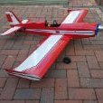
Caveman Posted January 22, 2018 Share Posted January 22, 2018 HI, i agree with Paul, spats and longish grass are probably not a good mix! This is my CAP 20 L, from Peter's plan but increased in size by 12% ( I had an Irvine 46 with Pitts exhaust, and as the plan was originally based on a 32 I went for a larger airframe) It's based on a this full size example: I felt that as the full size plane didn't have spats I was justified in keeping to the scale-look and left them off. Cheers GDB PS Mine's now got an aluminium spinner in place of the white plastic one, even more scale! Quote Link to comment Share on other sites More sharing options...
Paul C. Posted January 22, 2018 Author Share Posted January 22, 2018 Couldn’t resist a trial fitting of the canopy, the Vortex canopy is an excellent fit. Quote Link to comment Share on other sites More sharing options...
Paul C. Posted January 22, 2018 Author Share Posted January 22, 2018 Nice one Caveman, I was thinking of increasing the size but I decided against it as I wanted to crack on with the build. did you use the Vortex canopy or did you have to make your own, ally spinner is a must for this model Paul. Quote Link to comment Share on other sites More sharing options...
Paul C. Posted January 22, 2018 Author Share Posted January 22, 2018 Had a few rethinks on the removable cowl finally settled on cutting the side cheeks, front part attached to the cowl and rears attached to the fus. Two bolts through the cheeks onto captive nuts in the cowl, will post a picture as I can’t understand what I have just typed. Quote Link to comment Share on other sites More sharing options...
kc Posted January 22, 2018 Share Posted January 22, 2018 Greg, there is a bit about making spats here on the DB Sport & Scale website. Some books show this too and they usually show a big chunk ( or layers) of balsa with a wheel size semi circle fresawn out and then laminated with ply or balsa Never done it myself as we have rough grass strips at my clubs. Quote Link to comment Share on other sites More sharing options...
Paul C. Posted January 22, 2018 Author Share Posted January 22, 2018 As the weekend was a total weather washout and the wife had no intention of leaving the house a window of opportunity opened for me to blitz the wings. Heater on full and plenty of hot coffee let battle commence. As I had previously cut out all the ribs, cut spars to length etc pretty much made a kit, it was a straight forward assembly job. Followed Peter’s wing building method [there is a link in a previous post]. Using a mixture of Aliphatic and cyno the wings just literally flew together [no pun intended], the only changes I made was for wing mounted servos, added a piece of ¼ balsa between the first two wing ribs where the dihedral brace sits to give more glue surface. When I was laminating the tips I decided to insert a cocktail stick where it tapers at the aileron, my theory is that will be an area that can easily get damaged and the cocktail stick will beef it up a bit. Quote Link to comment Share on other sites More sharing options...
Paul C. Posted January 22, 2018 Author Share Posted January 22, 2018 Don't forget you need one port and one starboard wing NOT two the same Quote Link to comment Share on other sites More sharing options...
Paul C. Posted January 22, 2018 Author Share Posted January 22, 2018 While I was waiting for the glue to dry I decided to put the tank together, my preference is to use two clunks. One for the feed and the other for fill/drain the third pipe overflow/pressure, I use coloured fuel pipe so that I know which is which. Started doing this after I got the pipes mixed up and while blowing down them to try to work out the problem, ended up with a mouth full of 10% nitro not recommended. Quote Link to comment Share on other sites More sharing options...
Concorde Speedbird Posted January 22, 2018 Share Posted January 22, 2018 Nice neat work, I like a nice CAP. Quote Link to comment Share on other sites More sharing options...
Peter Miller Posted January 23, 2018 Share Posted January 23, 2018 I like the two clunk system too. But I don't put fuel in it and blow/suck!!! Quote Link to comment Share on other sites More sharing options...
Tim Ballinger Posted January 23, 2018 Share Posted January 23, 2018 Funny that Peter mentions Bowden cable. When I picked up modelling again I tried to to order some Bowden cable and was told ‘you sure you do not want a snake ‘ . I was a little confused for a while ! Tim Quote Link to comment Share on other sites More sharing options...
Peter Miller Posted January 23, 2018 Share Posted January 23, 2018 Yes, snakes. But they seem to be plastic in plastic apart from some Sullivan ones. Quote Link to comment Share on other sites More sharing options...
Caveman Posted January 23, 2018 Share Posted January 23, 2018 Hi Paul, I haven't progressed to making canopies yet, so I used the 'standard' Vortex canopy and with a bit of careful trimming it does the job quite nicely. Although it's smaller than scale (?) who would know? Here it is, complete with pilot and FrSky GPS unit. I do like the way you've designed the cowl. That should be a good sturdy fit, and easily removable. As I fitted my engine sideways I made the lower half fixed and the upper half removable. Also, note the Aluminium spinner - much better! Incidentally, although my first few flight were fine, take-offs and landings were not. The model nosed-over at the slightest provocation. I have now bent the legs much further forward and that's solved the problem. I don't know if I installed the leg mountings in the wing at the wrong angle, or what, but this is where the legs are currently. Just one more poimt; going back to the GPS unit installed, this shows that the plane is easily capable of well over 80 mph ground speed, and there's no hint of flutter, so perhaps the counter weighing is doing its job Cheers GDB Quote Link to comment Share on other sites More sharing options...

Recommended Posts
Join the conversation
You can post now and register later. If you have an account, sign in now to post with your account.
Note: Your post will require moderator approval before it will be visible.