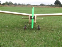
Dad_flyer Posted August 16, 2018 Share Posted August 16, 2018 Being a newbie to model flying I thought that the Mayfly from the article last month sounded very suitable, even more so when I found the original article from Model Airplane News. I have an experienced friend who has been more than helpful getting me into the air with a second hand foam high-wing. After getting careless and crashing, I found it hard to know where to find 'straight' on the foam to re-build the nose and motor mount - and obviously I had no plans. I have got it back into one piece, but I wanted to build a balsa model so that I would be able to make repairs more easily when needed. This is not really a build blog - it starts at the end: Does it fly? Yes. It was rather blustery but the Mayfly rose easily from the grass, did a circuit an landed safely (with experienced hands at the controls, not me...) I could not find anyone else building this other than the two original articles, so I shall post some more photos and details of decisions I made beyond the original plan. Quote Link to comment Share on other sites More sharing options...
Dad_flyer Posted August 16, 2018 Author Share Posted August 16, 2018 First up: How much Balsa would I need to buy? I have not got leftovers from previous projects, this is my first build other than a laser-cut kit fro a balsa and tissue rubber powered plane. With no good model shops left nearby it had to be an order from SLEC multiple delivery charges if I got it wrong. I ordered to much to be on the safe side, but it seems that I ended up using: 1/16" x 3" soft 4off (wings) 1/16" x 4" medium 1 off (top and bottom skins) 3/32" x 3" soft 1off (not sure now where that went!) 3/32" x 4" medium 2off (sides) 3/32" x 4" hard 1off (tail and stabilisers) 1/8" x 4" medium 1off 1/8" x4" hard 1off (very little used - wing tip plates) 3/16" x 3/16" hard 2 off (internal bracing and push rods) 3/16" x 1/4" hard 1off (wing leading edge) 1/8" hardwood dowel 1off 1/8" poplar plywood - very little used. (36" lengths for each of them) Second: Power plant: This is listed in the article, but also 4-max have recommended a set of motor-ESC-prop-battery which made fewer decisions. Helpfully they also give the thrust with 2s and the prop - at about 450g. The battery seems small for the maximum power and current of the motor, but the final weight seems to be going to be low, so the motor is probably far from full power. I got an even number of batteries to be able to run two in parallel if more capacity is needed. Finish: I really liked the look of the plain wood finish and wooden prop in the article. I was not able to find a wooden prop in the right size, and 4-max say to use only the plastic GWS props on that motor. The bright green is an acquired taste. I have never used sanding sealer, and again did not have a model shop to go to. I dithered over finish for ages - 'proper' sanding sealer or the water-based version? would the water based version give the nice golden finish or would it be whitish like the water based dope I used on tissue? I dithered so long that the model was finished and just used what I had to hand - ordinary varnish, being as thin as I could with two coats. I used a spray can clear lacquer for the tail with one dusting coat. All up weight is 435g 15.4oz including one little battery and 2.5 oz lead to balance it correctly (roofing sheet, around the motor housing wrapped in insulating tape in the photo) I did not have good enough scales during the building to really see whether the tail heavy is because of heavy varnish. I think if there had been enough extra weight to matter, I would have been able to measure it. Quote Link to comment Share on other sites More sharing options...
Dad_flyer Posted August 16, 2018 Author Share Posted August 16, 2018 Before more build details, a question: Clearly the nose lead is a waste of weight, I have three thoughts. One is put in a bigger battery, but that would be further back than the weight is now, so would need to be heavier and would be more than 4 times bigger than the current battery and give a very long flight time. The motor has plenty of grunt for that, but it would make faster flight and heavier landings. Second would be to build a box in the motor bay to put the motor further forward, and get the battery and ESC in front of the current firewall. Third would be to shuffle the wing back a little. This third seems the most sensible and it feels as though it should be quite easy to do on this plan. Fourth would have been to build the tail lighter in the first place, but I don't see obvious weight savings there. It flew well anyway, so will stay as it is for a bit. Any suggestions welcome. Edited By Dad_flyer on 16/08/2018 17:49:03 Quote Link to comment Share on other sites More sharing options...
Dad_flyer Posted August 16, 2018 Author Share Posted August 16, 2018 I am very pleased with the wheels. I forgot to add any undercarriage parts to any of my orders for this model, so I had to improvise. I had a piece of 1/16" aluminium, and I found a couple of bolts in a random tin with threaded ends and a smooth middle. I even found matching nuts for them. The nuts are glued to stop them shaking loose. The 'lightening' holes are totally unnecessary, but look right. The wheels are three sheets of 1/8" balsa, glued together cross grained. Covered with tissue and EZdope, with black insulating tape for tyres. Initially I just made the central hole in the balsa wheel and hardened it with thin superglue, but that did not survive even a light test throw. I got some hexagonal PCB spacers with about the right diameter central hole and enlarged the hole in the wheels to accommodate them in a tight fit. Superglue run in round the edges and then epoxy on the sides. Wheels are held to the axles with half a section of electrical choc-strip (wheel collets also not ordered). This has survived the maiden flight, with taxi on the grass and landing. I can always make new wheels or buy some if they do not last well. I need to paint the hub epoxy black to make it look neat. 6g for each 2.5" wheel, 38g for the whole assembly. Nice mix of unit systems there. Edited By Dad_flyer on 16/08/2018 18:20:27 Edited By Dad_flyer on 16/08/2018 18:29:58 Quote Link to comment Share on other sites More sharing options...
Dad_flyer Posted August 19, 2018 Author Share Posted August 19, 2018 During the build the biggest difficulty I had was fitting the radio gear and control rods, not because it was actually particularly tricky, but the plan is not very clear and I had not done rods before. There is also a geometry problem with the angled tail trailing edge and angled rudder. When the rudder moves, the control horn will kick up or down, not swinging in a straight line along the control direction. If the control horn is angled to the angle of the hinges then it swings straight, but you cannot get the control rod moving along that direction angled up from the level. This seems a slightly odd point in the design, the join between fin and rudder could have been vertical. Anyway, I enlarged a hole in the horn to 2mm and put a piano wire through without a clevis. This does not jam as the rudder rotates, but there is a little play at the neutral position. Once that was decided I had to route the control rods back to the servos. The route is very far from a straight line, as is shown on the plan. I was not sure how to make this work without bending. In the end I realised that the plan implies a short metal rod at each end, with a straight balsa rod in the middle. This has a great advantage of meaning that the two ends are bent alone, and the overall length can be easily set by the length of rod inserted into the balsa before final gluing. Two cheapo 9g servos on a 1/8" ply board for the control - I got them for a land-based project where failure does not matter so much. I hope they stand up to service in the air! The holes are very untidy - I forgot to put holes in the formers before joining the fuselage together. Quote Link to comment Share on other sites More sharing options...
Dad_flyer Posted August 21, 2018 Author Share Posted August 21, 2018 Flying again this evening. Rather long grass so tried hand launching... ...which ended back in the pits gluing the tail back on.Next time we found the shortest grass and she managed to rise.It was nice and calm, so I got my own hands on the controls for the first time. She is lovely to fly for a beginner. When I panicked a couple of times I let go of the sticks and she sorted herself out straight and level.Glide on no power was so docile that I was allowed to try approach and landing. My first time bringing in any model successfully completed.Went through four 450mAh 2s, getting 6 minutes plus for each.No trim added. Goes a little left under power but seems to glide straight. I did not build in any right thrust, so I shall try a couple of washers as suggested on the plan.Edited By Dad_flyer on 21/08/2018 23:01:14 Quote Link to comment Share on other sites More sharing options...
Piers Bowlan Posted August 22, 2018 Share Posted August 22, 2018 Good stuff Dad Flyer, I like your improvisation. Regarding the nose weight, as you pointed out, the plan calls for a balsa pushrod which may save a couple of grams down the back end, which is worth several grams in the front but you may still need some lead in the nose. As you pointed out a larger battery is preferable to lead if only you can locate it far enough forward. Your 450mAh 2s Lipo probably weighs about 30g or there abouts. If you were to use a 1000mAh capacity Lipo which would weigh under 60g (because it would have the same cables/plugs) it could probably be installed so that it was flat up (vertically) against the back of the motor bulkhead using velcro or suchlike. Looking at the plan on Outerzone the motor bulkhead is 75mm deep (just under 3in) so if you google 1000mAh 2s LiPo you will find several that will fit, when mounted this way. (In fact I have a 1300mAh LiPo that would fit) You may find that you can then remove the lead and might be a better solution than hacking holes in the motor bulkhead. A larger capacity LiPo might also give you a little more power, as well as duration, as it has a lower internal resistance. As you say, you could also trying moving the wing rearwards as the model has a very short nose moment but this may not be an elegant solution. Regarding the swept fin and rudder, theoretically a backwards swept rudder causes a down force on the tail when deflected. On your model the yaw induces roll and the further effect of roll is for the nose to drop. This is why a swept fin might be beneficial, - it tends to keep the nose up in the turns without requiring so much elevator. I say might because it depends on how much you bank, how fast you are flying and a load of other variables. There are good reasons why swept fins are added to airliners but I am convinced the main reason why designers incorporate swept fins and rudders on models and light aircraft for that matter, is that they look cool! Your linkage obviously works Dad Flyer so why change it? If you are faced with that problem again in the future you could consider a ball link and metal clevis which would have less slop than your arrangement. Alternatively just fit your own vertical fin/rudder hinge arrangement, it will probably work just as well (better?). Edited By Piers Bowlan on 22/08/2018 08:06:42 Quote Link to comment Share on other sites More sharing options...
Dad_flyer Posted August 22, 2018 Author Share Posted August 22, 2018 Piers, thank you for the explanation of the swept tail geometry as a built in rudder-elevator mix. I did a quick calculation for moving the wing back. It seems that it might need to be as much as an inch back, which would go from a short nose to quite a long one.Given the successful flights so far, I shall leave well alone. Particularly as the landings are not too fast and the undercarriage has stood up to the extra weight.Edited By Dad_flyer on 22/08/2018 09:06:38 Quote Link to comment Share on other sites More sharing options...
Piers Bowlan Posted August 22, 2018 Share Posted August 22, 2018 A man after my own heart, - If it ain't broke don't fix it! Quote Link to comment Share on other sites More sharing options...
Dad_flyer Posted October 13, 2018 Author Share Posted October 13, 2018 I have only been able to get to the patch twice more since the last post. Both times Mayfly flew, and I was able to do both take-off and landing - my first full flights . One day was rather windy, even much bigger models were feeling it. Being light and slow Mayfly ballooned a lot head to wind, giving lots of elevator practice. The other day was calm and had 6 lovely flights. I did a bit of research on the design weight to understand my extra nose weight for balancing. I had 50g+ lead by the motor. However that motor only weighs 25g, and Mayfly was designed for the Cox 049 which is twice the weight. Then the receiver batteries probably weighed more than the 450mAh 2s lipo I used to start with. So probably my build was OK after all. I have doubled the battery (either two 450 in parallel or one 1000mAh), and put them as far forward as possible. That removed about 30g of lead. With the extra battery I was getting to the limit of concentration well before running out of battery. Edited By Dad_flyer on 13/10/2018 22:47:35 Quote Link to comment Share on other sites More sharing options...
Dad_flyer Posted January 5, 2019 Author Share Posted January 5, 2019 This has been a lovely model for getting up without a buddy and getting stick time. Child_flyer is confident on it too, take-off to landing. Mostly flying 1000mAh 2s now, with long flights. It balloons quite a lot into a headwind or on high throttle, which is really what limits how much wind it is comfortable to fly in before the elevator control becomes trying. A bit over 10mph forecast wind is ok, which is the least we had throughout the autumn. Lovely and calm out today, the first of the calm days I have been able to get out over the break. I must have been lying on my side... Edited By Dad_flyer on 05/01/2019 17:54:07 Quote Link to comment Share on other sites More sharing options...
Dad_flyer Posted April 20, 2019 Author Share Posted April 20, 2019 A lovely evening flying, slightly marred by a tree which jumped out on me... the tail... and the nose. The wings are fine. I have all the bits, a pot of superphatic and a spare prop. Quote Link to comment Share on other sites More sharing options...
Dad_flyer Posted April 21, 2019 Author Share Posted April 21, 2019 Successfully re-maidened this evening. Quote Link to comment Share on other sites More sharing options...
GrahamWh Posted April 21, 2019 Share Posted April 21, 2019 Well done Dad_flyer. If you made it, you can fix it! Quote Link to comment Share on other sites More sharing options...
Dad_flyer Posted April 21, 2019 Author Share Posted April 21, 2019 Quote Link to comment Share on other sites More sharing options...
Dad_flyer Posted May 12, 2019 Author Share Posted May 12, 2019 Elevator pushrod started clunking. I first thought it was binding somewhere, but actually it was the cheapo unbranded servos (post 5). So replaced those with new ones from the 4-Max range. One metal gear, the other plastic. Much smoother than the others were, even when new, and cheaper too. And noticeably stronger. Quote Link to comment Share on other sites More sharing options...
Dad_flyer Posted June 15, 2019 Author Share Posted June 15, 2019 After being my no-buddy-box trainer, and some hanger accidents, Mayfly is a little worse for wear. Wing dents / splits and both tip plates broken. As well as that the control linkages are very sloppy, being my first attempt at anything like that. Also the horizontal stabilizer has twisted. So it is time to use the poor weather for a refurb. I have removed the vertical stabilizer and wetted the horizontal stab with ammonia water. Now it is weighted flat and drying. If it comes out ok, good. Otherwise I shall make a new one. After success with tissue and dope over sheet balsa on another build, I shall cover Mayfly that way as well. It should give a harder finish and might reduce splitting along the grain. Finally I shall put in ball links (the rudder is slanted) and snakes to make the control more positive. We shall see if it all works. Quote Link to comment Share on other sites More sharing options...
Dad_flyer Posted August 8, 2019 Author Share Posted August 8, 2019 It worked so well that I forgot to post here. Removed the vertical stab. And the control rods. It is lightly varnished, but not too waterproof. I was able to wet with diluted ammonia cleaner. After pressing on a flat surface to dry for about a week it came out OK. At least, a lot less twisted. Coated with sanding sealer and light brown tissue with dope.the tissue really brings out the wood colour, and you can only see it is tissue from the darker overlaps. Quote Link to comment Share on other sites More sharing options...
Dad_flyer Posted August 8, 2019 Author Share Posted August 8, 2019 Then fitted snakes and ball links to replace the wobbly rods. The ball is necessary on the rudder as the hinge line is tilted. The new control runs give far more positive reaction to stick inputs. The covered surfaces have much better ding resistance and feel stiffer as well. Overall this did make the tail heavier, so now she has to fly with a second 1000mAh 2s up front as ballast. Still flies better than when first built so I am pleased with the upgrades. Quote Link to comment Share on other sites More sharing options...
Dad_flyer Posted August 8, 2019 Author Share Posted August 8, 2019 That was all a while ago. Finally got round to replacing the wing tip plates and covering the wing and the forward fuselage. Took the wheels off to hand launch and belly land with this long grass! I do like this model, so does child_flyer. Quote Link to comment Share on other sites More sharing options...
Dad_flyer Posted April 4, 2020 Author Share Posted April 4, 2020 Going through my repair list as well as sorting out where I had got to in stalled builds. I notice the warp has come back in the horizontal stab on Mayfly. The plan calls for 3/32 hard. This is quite thin, but also has some weight. I have gone through my new balsa stock and I have some nice light 1/8 and 3/16. The 3/16 soft is about the same weight as 3/32 hard that I used. With the thicker section will it be less prone to warp? The covering (tissue and dope) will be held further apart, which ought to give more stiffness. Quote Link to comment Share on other sites More sharing options...
Dad_flyer Posted April 4, 2020 Author Share Posted April 4, 2020 I think I have an answer to my own question. I have sheet of 1/8 at 36g and a sheet of 3/32 at 44g. Putting one end on the table for 6", the 3/32 droops more when one way up, and about the same when the other way up (the 1/8 has the same droop both ways). Keeping the one end on the table, I then tried to feel the resistance to twist. Harder to judge, but the 1/8 did seem stiffer in twist. Covering must add more stability to the thicker sheet than the thinner, so I shall go with that and save some weight. I don't think 3/16 will be necessary, though it would still be very little heavier than the 3/32. Quote Link to comment Share on other sites More sharing options...
fly boy3 Posted April 4, 2020 Share Posted April 4, 2020 Hi Dad-flyer, many years ago when every one was building, I came across a tip to prevent a warp in solid balsa elevators. IIRC, a rectangle of a suitable size was cut out of the middle of the elevator. This was replaced by an exactly sized and same thickness piece of balsa, but glued back with the grain at 90 degrees to grain of elevator. Worked for me. Cheers Edited By fly boy3 on 04/04/2020 22:40:38 Quote Link to comment Share on other sites More sharing options...
Dad_flyer Posted April 4, 2020 Author Share Posted April 4, 2020 Thanks Flyboy. I have seen that on some plans. This one has tip plates which will stop bowing, but probably not twisting. I wonder whether retro-fitting those cross plates in my twisted stabiliser might hold it back flatter? Probably holding in some extra reverse twist whilst glueing. Not good engineering to build in opposing stresses, but if the real remedy is replacing the whole thing, then trying butchery might be an interesting experiment. I think it was just designed a bit thin in the first place. My other stalled build is the same size and has 1/8" thick fin and stab, the Peter Miller Miss Deeds that is to come after that is 50% bigger with chunky 1/4" tail feathers. Quote Link to comment Share on other sites More sharing options...
Dad_flyer Posted April 13, 2020 Author Share Posted April 13, 2020 This is the extent of the twist in the horizontal stabiliser. The picture makes it look better than it really is. I cut a couple of biggish holes in the stab, but it is still stiff to twist, so I think replacement is the only option. Butchery commenced before I loose my nerve. Quote Link to comment Share on other sites More sharing options...

Recommended Posts
Join the conversation
You can post now and register later. If you have an account, sign in now to post with your account.
Note: Your post will require moderator approval before it will be visible.