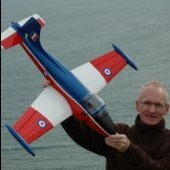
Steve Houghton Posted November 4, 2019 Share Posted November 4, 2019 My subject for the 2020 PSSA mass build is this scintillating CA-27 operated by the TNI-AU or Indonesian Airforce Display Team, known as Spirit 78. This is a modified variant of the F86-F but powered by a Rolls Royce Avon engine (it's British, don't you know!). The fuselage was deepened and the intake widened, but I shall be exercising builder's licence to just use the standard plan version because I like the colours. It was faster than the US versions, and sported twin 30mm cannons instead of the usual 6 machine guns - handy if the crowd gets nasty during a flying display! If I can master the painting of the curves, it should look something like this: Quote Link to comment Share on other sites More sharing options...
Martin Gay Posted November 4, 2019 Share Posted November 4, 2019 Nice! I've not seen that scheme before. Quote Link to comment Share on other sites More sharing options...
Andy Meade Posted November 4, 2019 Share Posted November 4, 2019 hehe - excellent introduction there Steve Great colours too! Quote Link to comment Share on other sites More sharing options...
Steve Houghton Posted November 4, 2019 Author Share Posted November 4, 2019 Thanks, Guys. The first fuselage half is well under way. I hope to post a few pics tomorrow, Quote Link to comment Share on other sites More sharing options...
Steve Houghton Posted November 5, 2019 Author Share Posted November 5, 2019 Wing Bolt Plate Doing a dry fit of fuselage parts I noticed that WP1 as cut in the kit, and shown on the plan view, does not butt up flush against F7 when inserted into the slots in F14. I therefore cut 3/16" off each tab and epoxied the bits onto the front, to move the tabs forward and allow WP1 to sit back against F7. It now fits flush, and could be reinforced with triangle strip if necessary: I believe this is correct according to the fuselage side view of WP1: Side by Side I then ploughed on with assembling the first fuselage side. I chose to laminate the bottom keel from two pieces of 1/8 x 1/8 to create the curvature, and to align and glue the formers against this before adding the top keel: However, this resulted in a slight mis-alignment of the tops of the formers with the top keel, which is straight. I lengthened the slots in F9 and F10 to the same 6mm width as the keel, and managed to get it all to fit: The only small issue I had was trying to hold down the part-formers F3 and F5 and keep them vertical. I therefore fitted them at the same time as adding the stringers, and applied suitable weights onto the stringers (not shown). Now onto some planking..... Quote Link to comment Share on other sites More sharing options...
Martin Gay Posted November 5, 2019 Share Posted November 5, 2019 Looking good Steve. Quote Link to comment Share on other sites More sharing options...
Harry Twist Posted November 5, 2019 Share Posted November 5, 2019 Looking tidy that Steve, nice choice of scheme also. Your intro has got me wanting to read up on the Avon Sabre - didn't realise fitment involved fuselage mods! Quote Link to comment Share on other sites More sharing options...
Steve Houghton Posted November 6, 2019 Author Share Posted November 6, 2019 Thanks for the comments. Harry; Mark has posted a few videos of the CAC Avon Sabre, on his Sabre F86 thread, if you want to see more. Meanwhile.. Get planking I have never planked before, so this is a step into the unknown. Where to put the first strips?? I decided to put them straddling the central stringer. They don't follow the stringer route exactly as I allowed them to 'relax' into place without too much twisting and resultant in-built tension in the frame. I am trying to use tapered planks, approx 8mm in the middle, tapering to 5mm at the nose and 3mm at the tail. Whether this will work for all of them I don't know but it'll be exciting finding out: Accommodating the sharp tail curvature is going to be the biggest challenge, hence the narrow strips: Quote Link to comment Share on other sites More sharing options...
Steve Houghton Posted November 8, 2019 Author Share Posted November 8, 2019 Part Planked One complete sheet of 1/8 x 3 x 48 has now been dissected into thin tapered strips and applied to the fuselage. The nose and tail now look like this: The tapered strips are working well, but I don't yet know if they'll be practical as the curvature tightens up. Tracing the way ahead I'm going to start the second fuselage half before completing this one, so that I can check that the two halves align accurately. Just visible in the photo above is a sheet of tracing paper underneath this half. I traced around the framework and then laid it upside down onto the second fuselage half on the plan to check that everything was going to line up. There are minor discrepancies, as expected, but I'll build onto the tracing to hope they match: I think the main aim is for the two halves of F4 and F7 to align accurately at the wing seat, where fellow F86'ers will be able to spot any mistakes! Quote Link to comment Share on other sites More sharing options...
Martin Gay Posted November 8, 2019 Share Posted November 8, 2019 Steve, If you leave the last few planks off at the top and bottom of each side it will be easier to align the two halves. Clamps can be used along the keel pieces whilst the glue dries as well. Don't forget to add the battery box and WP1 before joining the fuselage! Martin. Quote Link to comment Share on other sites More sharing options...
Steve Houghton Posted November 9, 2019 Author Share Posted November 9, 2019 Thanks, Martin. I did wonder about leaving the last planks until after joining, but with the aim of smoothing over the join line. I'd forgotten about being able to clamp them, so thanks for the reminder. Quote Link to comment Share on other sites More sharing options...
Steve Houghton Posted November 10, 2019 Author Share Posted November 10, 2019 Dry Bones The basic frame of the RHS fuselage has been assembled and dried overnight without any planking. I couldn't resist a dry fit of the two halves to check the match. The top of the nose looks OK: The cockpit area is reasonable: F1 and F10 are nicely square and in line: Overall, the wing seat is acceptable, in that the centres of the formers line up: However, F7 and F4 are slightly angled. I think I was too zealous in sanding the ends of F14 on the first half, resulting in shortening it a fraction. I didn't notice during the dry assembly of the second side, but the second F14 must have been a fraction longer and caused F4 and F7 to be slightly splayed apart when I aligned their inner edges with the tracing of the first side. Here's the backwards kink in F7: Similar kink forwards in F4: One side of F4 is therefore a little crooked, where the light is shining through below. I might have to apply a thin shim of wood to level the rear edge a bit, but that'll come later. Work Assessment Overall, 7/10 so far for effort, but could do better. I'll return to planking for a few days now. Quote Link to comment Share on other sites More sharing options...
Phil Cooke Posted November 10, 2019 Share Posted November 10, 2019 It all looks very neat and accurate to me Steve - great progress... seems the fuelage comes together quite quickly - impressive stuff! I'm still fettling the Jet Provost 150 here so not planning to make a start on my Sabre quite just yet - but I'm conscious of being left behind! Quote Link to comment Share on other sites More sharing options...
Steve Houghton Posted November 10, 2019 Author Share Posted November 10, 2019 Thanks Phil, Yes, the fuselage is a very satisfying build, which I am really enjoying. Great design work by Martin and Gordon. In case the message is hidden in my last post: I recommend builders to check that F14 is the same length on both fuselage sides, after you've fettled it to fit the slots in F4 and F7. I'm not suggesting any problem with the kitted parts, just my finger trouble. Phil, I'm jealous of your masterful work on the JP canopy. I've revisited my Zlin 526 canopy recently, without much success yet - I'll post an update when I can (completion will soon be as late as your Hog!). Perhaps you should offer an article to RCM&E about your method - it always seems to achieve stonking results. Quote Link to comment Share on other sites More sharing options...
Chris Barlow Posted November 11, 2019 Share Posted November 11, 2019 I'd give you at least 8/10 for effort Steve. Good tidy progress there. I have added some beginner friendly tips for planking on my blog if you need any entertainment! Quote Link to comment Share on other sites More sharing options...
Steve Houghton Posted November 11, 2019 Author Share Posted November 11, 2019 Chris, Thanks for the 10 planking tips - very useful. I've planked as far as the edges of the tight corners, and not sure I can twist the planks round without tapering. It may be a case of much narrower planks, almost strips, to negotiate the curvature. Quote Link to comment Share on other sites More sharing options...
Martin Gay Posted November 11, 2019 Share Posted November 11, 2019 Hi Steve, I chose to use a herringbone type pattern and trim the planks to fit where they touched! Quote Link to comment Share on other sites More sharing options...
Steve Houghton Posted November 11, 2019 Author Share Posted November 11, 2019 You experts all make it look so easy! Martin, I note that you have left the wing seat unplanked - I was wondering about that, and precisely how to cut out the wing seat area. Perhaps you could elaborate on the Gamma build blog, when you come to it? Quote Link to comment Share on other sites More sharing options...
Steve Houghton Posted January 17, 2020 Author Share Posted January 17, 2020 Running (walking!) Again! Following an unexpected delay to building, my progress continues slowly. Both fuselage halves are now planked apart from the gaps for joining, and the wing seat. The photos show my tapered planks, seemimgly much narrower than other builders have used, but it worked for me. The tail end: Wing Seat: Lower nose: Upper nose: That sinking Feeling A few planks sank and ended up looking 'starved', so I just layed a few strips of 1/16 to fill the depressions: Making two halves into a whole I'm thinking through the fuselage joining phase. I plan to use closed loop for rudder control and will install a couple of tubes to guide the cables, once I decide where the servos will go. For elevator control I'm planning to use a solid pushrod. I've done a few dry runs and believe I can install it after joining the two halves. There is enough wiggle room to poke the rear end up through the slot for the bellcrank, couple it up and then fix the crank into position. That's the theory! If not, I'll need some surgery to open a hole in the fuselage. Quote Link to comment Share on other sites More sharing options...
McG 6969 Posted January 17, 2020 Share Posted January 17, 2020 Hi Steve, Nice to have you back at the building board... and already close to join your fuse halves. Cheers Chris Quote Link to comment Share on other sites More sharing options...
Steve Houghton Posted January 18, 2020 Author Share Posted January 18, 2020 Chris, thanks for the reply. A quick update from today's progress, although nothing that hasn't been covered elsewhere. Give me your support The tubes for the closed loop rudder wires are supported quite high up by the addition of a filler into F8, to keep the runs as straight as possible: The remaining supports won't be fitted until after joining the fuselage, as they will be accessible from the wing seat and I'll be able to see better where they need to be. I like to connect the wires to the servo via a 180degree belllcrank so that the wires can be tightened without straining the servo bearings. Mounting this will need better visibility of the equipment bay layout later on. The wing bolt mounting plate has been fitted to one side, using a dry assembly of the two halves to ensure it was aligned: The battery box was glued into one side, using a couple of scrap balsa supports to hold it still: Join me now Finally, the grand fuselage joining ceremony, with support from the faithful Irwin clamps and some scrap balsa blocks, tapered to accommodate the fuselage taper: Ssssteam Heat Dry assembly revealed that both halves had banana'd slightly outwards during the planking phase, especially at the nose. Before joining, I therefore steamed the sides a little to allow them to bend in before clamping: That'll be left to dry overnight to ensure the glue can hold the tension. Quote Link to comment Share on other sites More sharing options...
Phil Cooke Posted January 18, 2020 Share Posted January 18, 2020 Very neat work Steve - your planking looks the business! Excellent stuff!! Quote Link to comment Share on other sites More sharing options...
Chris Barlow Posted January 19, 2020 Share Posted January 19, 2020 Good to see progress on the Sabre builds again Steve. It's a landmark step when you get the joined halves out of the clamps and have a full fuselage to work with. Quote Link to comment Share on other sites More sharing options...
Steve Houghton Posted January 20, 2020 Author Share Posted January 20, 2020 Thanks, Phil and Chris. I'm following both your builds with interest to compare notes. A Bender I don't know about others, but my pet hate in any build is bending wire, so I wasn't looking forward to the tailplane joiners. That's probably because a small bench vice is my only bending facility, and it's a struggle with anything thicker than 12g wire, because the whole table tends to move or lift when I put my weight behind it: Rejects Hence, I went through several rejected attempts before I achieved a successful set of front 8g and rear 10g joiners complete with embedded tube AND the correct angles. I usually managed to bend the central part, so that it wouldn't rotate in the tube, or I flattened the tube itself. The final best results came from using the smallest possible wooden lever (see above), and much brute force (Anyone know the best treatment for pressure blisters on fingers?): How have the rest of you expert benders accomplished this daunting task? I was intending to fit brass tubes into the tailplane halves, to make them removable, but I saw that some builders are planning to glue them in place. My worry with removable halves is that the wire joiners can slip sideways and the bends can bind on the central tubes, preventing rotation. Not sure how to prevent this yet. Quote Link to comment Share on other sites More sharing options...
Martin Gay Posted January 21, 2020 Share Posted January 21, 2020 Steve, I would advise against gluing the tailplanes on. The prototype model has flown in 12mph winds all the way up to 45+mph without any issues with the tailplanes moving sideways. If you have any worries then an application of a tiny bit of "Pritt-Stick" glue to the joiner will ensure that the tailplanes stay on. Being able to remove them also helps with storing the model! Martin. Quote Link to comment Share on other sites More sharing options...

Recommended Posts
Join the conversation
You can post now and register later. If you have an account, sign in now to post with your account.
Note: Your post will require moderator approval before it will be visible.