
Keith Jackson builds a new aerobatic biplane and tests out the Flight Coach F3A software and hardware.
words >> Keith Jackson
photos >> Keith Jackson & Lassi Nurila
Enjoy more RCM&E Magazine reading every month.
Click here to subscribe & save.
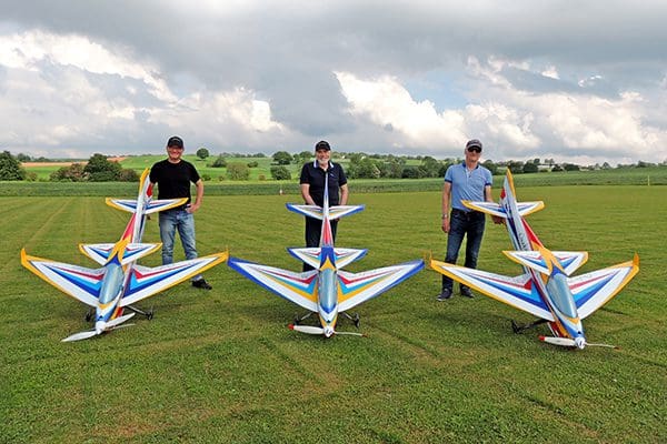
The Glacial biplane has been developed by Lassi Nurila over a number of years since his very successful re-design of the Gernot Bruckmann Sensation. I first became aware of the model in late 2020 when Lassi published pictures detailing the construction of the Glacial at his workshop in Finland. Lassi appeared to be really pushing the boundaries of construction techniques in terms of quality, accuracy, strength and weight, and I quickly became fascinated with his new design. After several conversations with Lassi regarding the Glacial, I decided to take the plunge…
FROM FINLAND
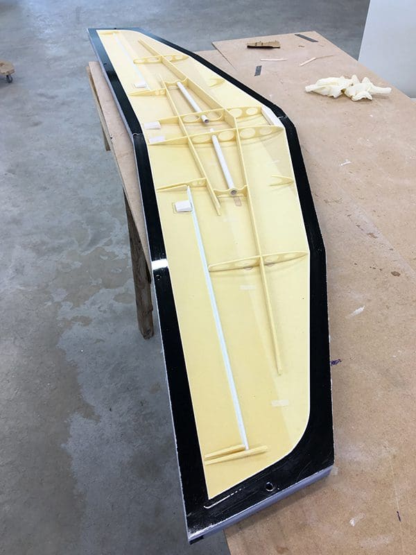
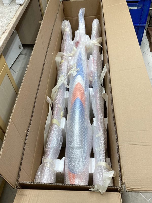
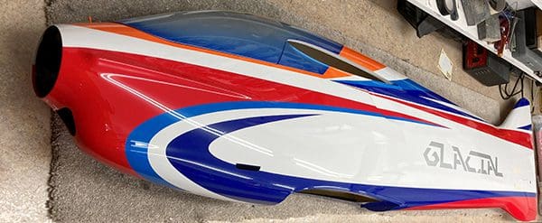
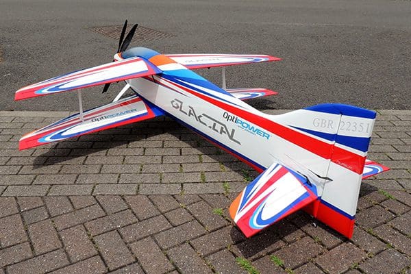
The Glacial arrived early January well packed in a huge box all the way from Finland. The actual model of the Glacial I received was a pre-production version, sent to me from Lassi but actually constructed by RC Composit (www.rc-composit.com) who’s previous F3A models include the Contrast and Europa. Lassi had spray painted the model, though it is intended that the Glacial will be painted whilst in the mould, as per the Angels Shadow or similar fully composite models.
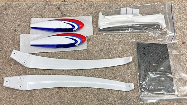
Unpacking the model held no real surprises and comprised a pair of wings, fuselage, canopy, wing struts, U/C legs and spats, and a carbon horn set. The first thing that struck me about these components were the lightness and the feel. These were fully composite parts, absolutely straight, painted and lacquered, were silky smooth and felt as though they had no significant mass to speak of. Absent were the multitude of screws, horns, clevises etc that normally arrive with ARF models, the main reason being modellers at this level would have their own preferences for installation, so rather than add cost to the package these items are to be sourced by the builder.
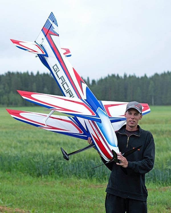
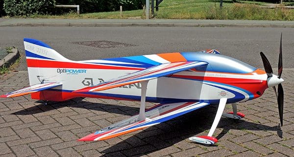
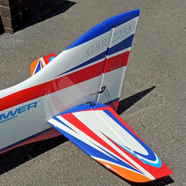
Moving away from the classic biplane look, the Glacial takes on the functional appearance of several biplane designs currently on the F3A market, such as the CA Models Andes II, Sebart Horu S and Skyleaf Leader. With the canopy located forward of the upper wing the fuselage is quite symmetrical, vertically speaking, in line with some concept designs such as Adrian Mansell’s Lepton design.
The wings have a particularly vogue profile, being swept, double taper affairs spanning 1.74m, with the second taper starting midspan and finishing with a conventional wing tip instead of the edge of the aileron. This latter feature helps enormously when setting up aileron trim. The section thickness at the wing tip is approximately 9.6%, which is slightly thicker than the 8% of the original Skyleaf Leader and should help to prevent the tips stalling during high G / high alpha manoeuvres.
MOTOR INSTALLATION
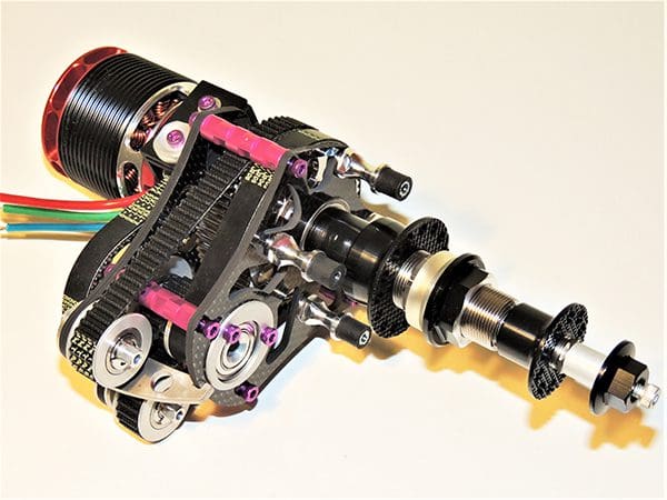
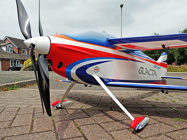
I tend to start F3A model builds with the motor installation, this being the most critical part of modern installations. Lassi had intended the Glacial to be powered by the very poplar and reliable Adverun contra drive and had supplied a carbon mount milled for just this purpose. However, readers of this column will know the high regard I have for the Akiba contra drive and having liberated my original drive from my BJ Craft Element prior to its sale, I now had one handy! This drive uses a Kontronik 650-78 780 kV motor, which drives Falcon 22” x 22” carbon propellers at around 4000 rpm.
Apart from the power and reliability of this drive unit the sound quality is wonderful and exceeds any other drive I have used in F3A.
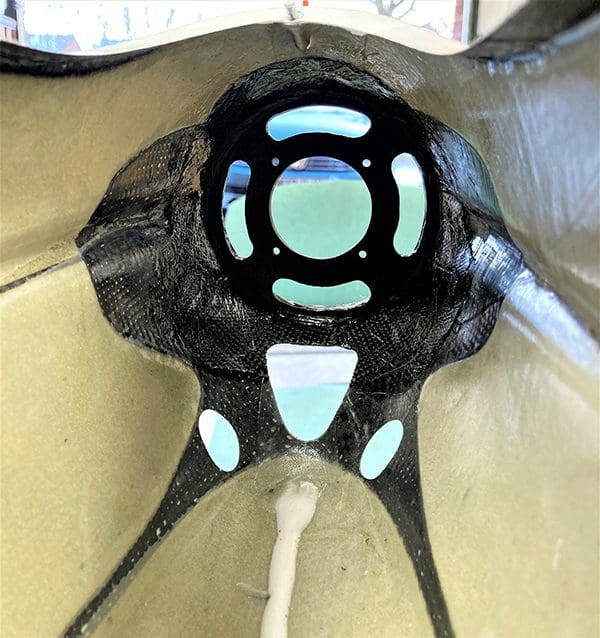
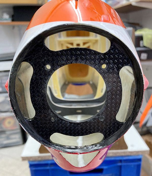
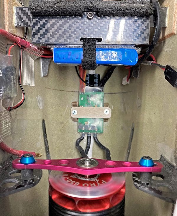
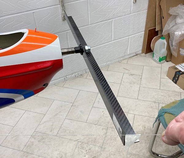
The front of the fuselage features significant carbon cloth reinforcement, which makes for a very rigid platform against which to mount the powertrain. A slightly modified ring mount was constructed from 3mm carbon plate and bonded into place using 24-hour epoxy with carbon tows used to form fillets front and back. The positioning and alignment of the drive is very important and great care is needed to ensure the contra drive is mounted with zero left or right thrust. To achieve this some angle carbon strip was fastened centrally to the contra drive prop shaft and the distance from each end measured from the fin to ensure accuracy.
Rear mounts for the contra drive were also fashioned from carbon plate and arranged to allow the contra drive unit to be easily accessed when installed. Similarly, the location of the D3 ESC was decided on the basis of ease of access and optimum cooling. Since the Akiba drive is physically quite large, the air intake would be partially blanked by one of its pulleys. So, I opted to cut into the floor of the fuselage, as I did previously with my Skyleaf Leader, and position the ESC with the heatsink outside of the fuselage. This is a but unconventional but works really well and has not led to any water ingress during those rainy flights we have in the UK.
RADIO INSTALLATION
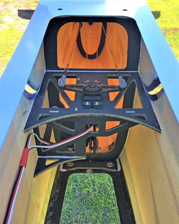
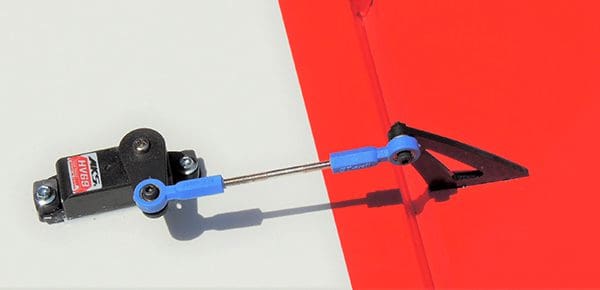
Installation in the Glacial was very straightforward with the exception of the centrally mounted rudder and elevator servos. These days it is conventional to have elevator servos mounted in the tailplanes and the rudder servo mounted locally at the rear fuselage. In this case, however, Lassi had meant for these servos to be mounted at the centre of the fuselage, requiring an unusual framework to support a vertically mounted rudder servo and a horizontally mounted elevator servo. Moreover, this latter servo was connected with the elevators via a double closed loop system. This helps to explain the horizontal mounting of the elevator servo since its horn would rotate in the same plane as the elevator horns. Lassi had used this system previously on his Sensation and it obviously worked well and was extremely light in comparison to other methods. Also, it meant that the single elevator servo would affect each elevator in exactly the same way, thereby removing any doubt concerning linearity when using twin servos to drive each elevator surface.
MKS servos were used throughout the Glacial, specifically HV 747 servos for rudder and elevator and HV 69 servos for the four ailerons. Optipower LiPos were used for both the radio equipment and main drive batteries.
Fully installed the flying weight, without the main flight packs (1120g), came out at 3696g. Lassi has since informed me that production kits are now painted in the mould instead of using conventional painting techniques and now weigh approximately 3525g ready to fly without flight batteries! This is simply an exceptional achievement for a fully composite, perfectly straight modern day F3A biplane.
I’ll aim to report on the flying characteristics of the Glacial in the next edition
FLIGHT COACH
Following from my last article, and the summary of Flight Coach kindly supplied by Thomas David, I wanted to add my own user experience of this ground-breaking software. I say ground-breaking as I do not believe we have seen such a game changer in F3A since the introduction of LiPo batteries for electric power, or even before that, moving from 35 MHz to 2.4 GHz.
The Flight Coach completely improves one of the major activities for all F3A pilots: Practice without feedback! The vast majority of F3A pilots put enormous amounts of time and energy into this activity, and whilst it absolutely does help to hone one’s skills, sadly, if you are not seeing the fundamental mistakes you consistently make then your improvement is bound to be limited. This often led to the phrase ‘glass ceiling’ being used about the lack of progress in the pilot’s F3A career and, more often than not, disillusionment. The feedback you receive from the Flight Coach currently relates to geometry, which dictates 60% of the scores you receive in competition, so it is hugely beneficial.
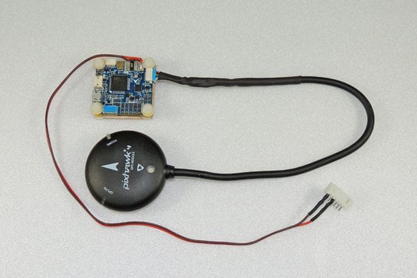
The Flight Coach requires both hardware and software to work in unison and an overview of the system would include:
- Hardware: Flight controller with integral data storage via a micro-SD card, and a GPS receiver with a built in Compass
- Ardupilot firmware: The Mission Planner program can be downloaded from https://ardupilot.org/. This allowed configuration of the Flight Controller by loading settings from the Mission Planner whilst it is connected to your PC via a micro-USB lead
- Flight Coach software: downloaded from https://www.flightcoach.org
The hardware I used was supplied by Phil Lewis, who is a Master pilot in the GBRCAA. This comprised a Flight Controller circuit board with a built-in micro-SD memory card slot, and a high-resolution GPS receiver. Power was supplied by connecting it to the balance leads of a flight battery and selecting the 2S pin to give approximately an 8.0V supply.
The hardware Phil supplied can be obtained from https://www.unmannedtechshop.co.uk/
HARDWARE INSTALLATION
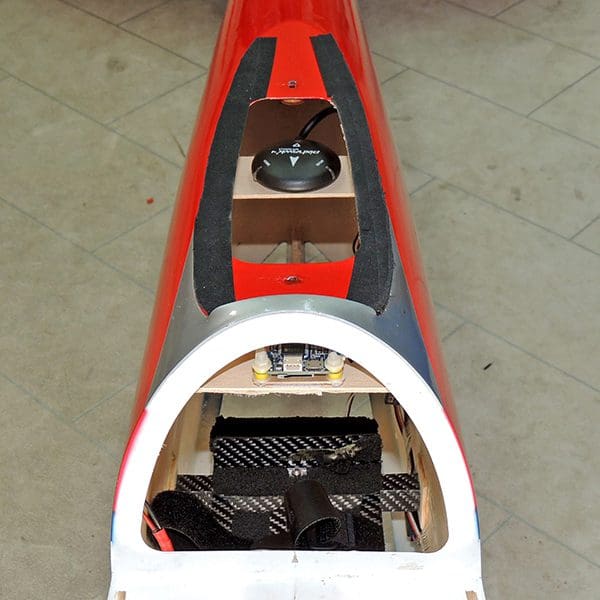
The hardware I used was supplied with the firmware software already loaded by Phil, so my remaining task was to install these into the model. The main requirement of the installation was to locate the GPS receiver as far away from the ESC/motor units as possible to reduce any electrical interference. In my case the Flight Controller was located just behind the canopy and this allowed me to access the micro-SD card easily for removal. I mounted it on a plywood shelf using Velcro should I need to remove the board from the model for any reason. The GPS receiver was located some way aft, just under the trailing edge of the upper wing. Access to this component would not normally be required so this was fastened with double sided adhesive tape to a plywood shelf.
The orientation of the Flight Controller and the GPS receiver is important, and arrows are shown on each component to aid installation. Ideally the arrows shown should point to the front of the model. However, different orientations can be accommodated by adjusting directional parameters in the Mission Planner setup.
The installation was checked with the Flight Controller connected by USB to my PC whilst running the Mission Planner program. In doing this, GPS data from my installation was displayed in real time and overlaid against a satellite image of my location. The orientation of the model was also checked and shown to be in agreement with the direction shown on the satellite image.
TEST FLIGHTS
First flight tests were conducted at my home site at South Cheshire RCS, in Middlewich. On connecting power to the Flight Controller, a blue status light shows that the system is armed and trying to read data from up to eight satellites. Once done the rapidly blinking blue LED on the Flight Controller circuit board changes to a once per second flash, indicating that the system is receiving GPS data and storing this on the micro-SD card. It is then down to the user to fly through a perfect F3A schedule, as anything less than precision is brutally shown up in the subsequent analysis. Once the flight is completed, the system is simply disarmed by disconnecting the power supply and flight data, stored during the flight in the form of BIN (binary) files, which are transferred to the PC via a micro-SD card reader.
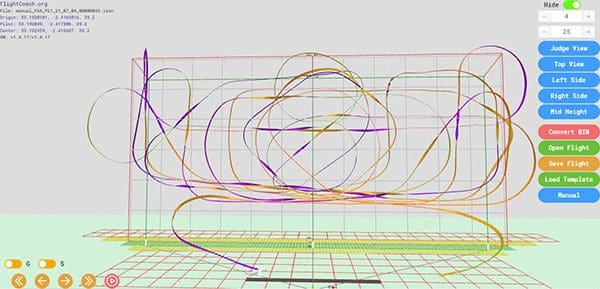
The next operation is to display the flight data in a meaningful way, and this is facilitated using the Flight Coach software and by selecting The Plotter tab. Selecting this brings up a generic 3-D representation of the flying area with the FAI box marked out from the pilot’s perspective.
The user then selects Convert BIN from the on-screen controls and this brings up a list of your stored flight data in a Windows explorer panel. On selecting the appropriate BIN file, the user is prompted for the aerobatic schedule flown and the details of the flying site where the flight data was recorded.
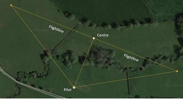
Incidentally, the location of the pilot position is required by the Flight Coach software and this can be easily obtained by zooming in on Google Maps or similar and reading the GPS coordinates to six decimal places. An additional reference location is also required, and the two positions are used by the Plotter software to align the flight data against the geometry of the flying site. (Aerial image of Keith’s flying site has been replaced by a graphic representation in the picture shown – KC)
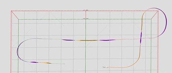
Once this data has been input the Plotter processes the flight data and displays the results in the form of a ribbon diagram. Initially, all of the flight data is displayed, making it difficult to understand. Fortunately, the Plotter has an additional function known as the Splitter and, as the name suggests, this splits the flight data into manageable chunks, which are displayed on screen, allowing individual or groups of manoeuvres to be viewed.
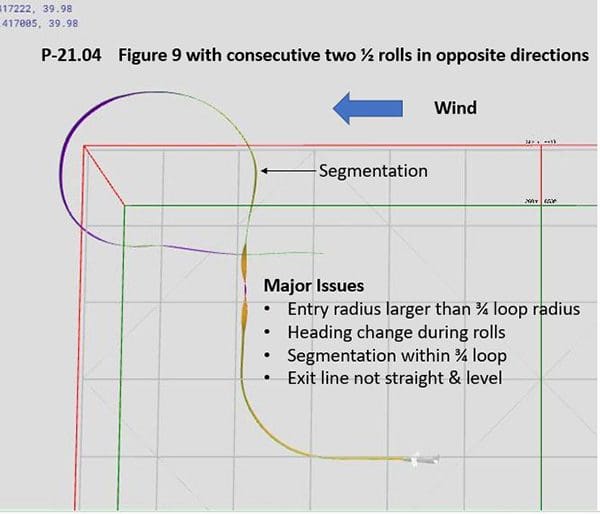
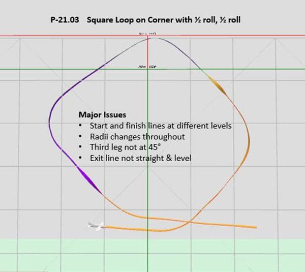
Projecting the individual manoeuvres against the background grid allows a multitude of mistakes to be highlighted, and it is indeed a sobering process. The following common mistakes are easily seen:
- Angles
- Line lengths
- Roll position in lines
- Lines not straight
- Baselines varying in height
- Diving or climbing into / within / out of manoeuvres
- Variation in radii (i.e., loop segmentation)
The flight representation can be re-played with the help of a small aircraft display which ‘flies” through the manoeuvres.
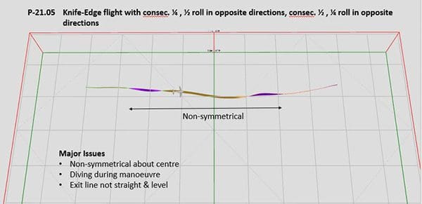
Trends are obvious and one I found in particular was diving in or between manoeuvres, which I simply wasn’t aware of, especially when at height such as in P-21.05 Knife-Edge flight.
I immediately found that all the above faults were affecting my flying in various ways and using this feedback I have been able to make several significant improvements. Also available are views from the top and each side of the flightline, and these are useful to show if the model is tracking in or out from the ideal path.


