Tony Nijhuis makes a welcome return to our Pro-Plan slot with his next series of EDF jets, starting with this exciting electric twin!
words >> Tony Nijhuis
words and photos >> Tony Nijhuis, David Ashby
Enjoy more RCM&E Magazine reading every month.
Click here to subscribe & save.
Following on from the little TSR2 in the April issue of RCM&E, which I have to say made a lot of builders very happy and was an amazing success, it’s time to use some twin power…
I think the reason for the success of the TSR2, and the previous tranche of 50mm EDF models, is due to the great little ducted fan units that are available now and the immense power they give.
As most seasoned modellers will know twin engine aircraft give better performance than the equivalent single engine. The same will be true for ducted fans and having dabbled with some new twin fan designs I have been impressed with the performance and, more importantly, their flight duration.
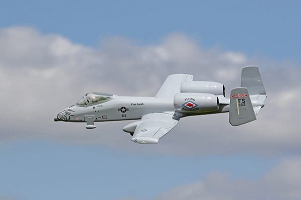
So, this new offering will be the first in a succession of twins, starting with the A-10 Thunderbolt II. What better way to start!
Tankbuster
I have wanted to do an A-10 for a long time now. It is one of the most requested models that I am asked to do. It must have been some 40 years ago when I built a single IC engine tractor version from an old paper plan that a friend had drawn on the back of some wallpaper. It had an OS 25FP on the front and it flew great. I always thought that one day it would be great to have a couple of ducted fans fitted to it. Unfortunately, no remnants of that old model exist anymore, so it was time for a new scratch built design. This is no bad thing, especially in these days of CAD.
Unlike the recent mini jet designs, where the wings are made of solid sheet balsa, this time I have gone for a built-up wing with a scale wing section. As a scale model this one is almost spot on, so even the most discerning scale modellers out there should be pretty pleased with this offering.
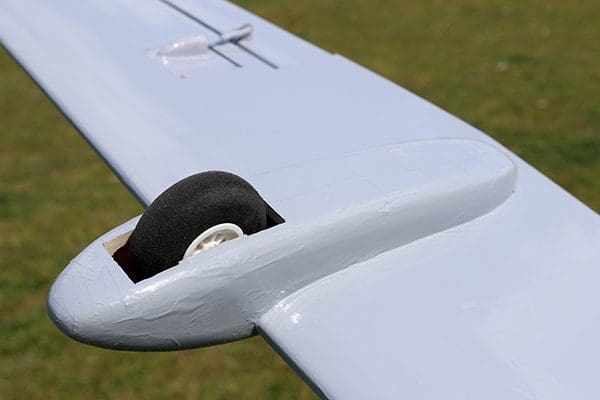
One thing that is a real bonus on this model is that it has no retractable undercarriage, but it will ROG (Rotate Off Grass). The scale retracted position of the main wheels still protrudes from the wing pods by 20mm, so this makes it a perfect tail dragger. As the model is only three channel (no rudders) it really is a case of pointing the model into wind, opening the throttle and away she’ll go! The model sits on the fins during take off so there are four points of contact, making it incredibly stable.
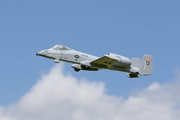
As I mentioned earlier twin-engine models are very efficient on power draw and the A-10 is no exception. Flying a scale schedule at scale speed you should easily get six to eight minutes, with the best duration being over nine minutes from a freshly charged 4000 mah 4S LiPo. So, what’s not to like about this model!
Similar to the single fan designs we have recently published, I decided that the 4S FMS/Power fun units would be ideal and give the best performance and duration – as long as throttle management is used.
As with all my models, and to assist the builder, I have once again made available a canopy and the front/rear vac forming for the engine pods. To complete the package a CNC/wood pack is also available for those who wish to make the building process a little easier and quicker. These parts will only be available through Tony Nijhuis Designs Ltd (TND) and not via MyTime Media. The plan itself will only be available in this edition of the magazine, with future copies again only being available again through TND Ltd.
A few other points to note:
The FMS/Powerfun fan units can be sourced from 4-max.co.uk in the UK. The batteries used were 4S 4000mah 30C LiPos and the servos were cheap and cheerful 10g metal gear minis. For the ESCs buy uncomplicated 40-amp 4S units as they will be lighter and hopefully have none of those unnecessary programming features. You want simple switch on and go types.
Lastly, and possibly the most important, a photographic build log is available as a free download to print out at: www.tonynijhuisdesigns.co.uk
These photos will be invaluable, and I would suggest downloading them so that you can familiarise yourself with the build before you start.
Fuselage
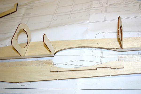
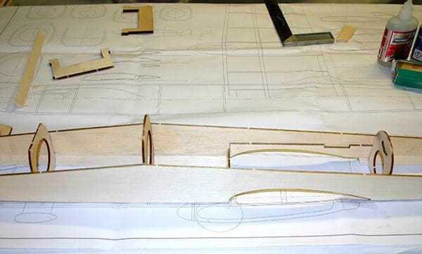
Begin cutting out the fuselage side FS1 and all formers F1 through to F8 and WS1. Mark the location of the formers onto the left and right-hand side of each fuselage side. Add strips of 9.5mm triangle along the bottom edge of the fuselage, as indicated on the plan, and glue into position WS1.
Fit the formers F3 to F6 to one side of the fuselage and then enclose with the other fuselage side. With the two N3s cut and trimmed, offer these up between F6 and F7 and glue into position, along with F7.
Add F8 and the top fuselage longeron between F4 and F8.
Then add formers F1, F2 and F3. You will need to make some saw cuts into the 9.5mm triangle to aid the bending of the fuselage between F1 and F3. The two top 5mm sq. stringers can now be added between F2 and F4.
The top of the fuselage can now be sheeted with 2.4mm soft balsa. It is worth wetting the outer surface of the sheeting to assist with bending. The best approach is to sheet in sections between F1 and F4, then F4 to F6, F7 to F8 and then, finally, between F6 and F7.
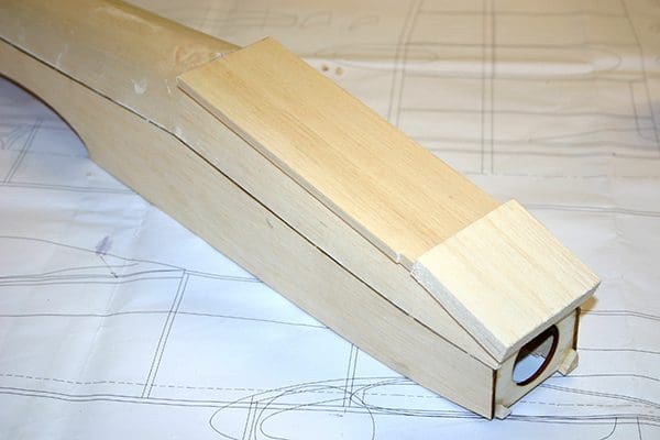
The front top and cockpit floor sheeting can now be added. You may wish to add the elevator control snake at this point. Add the front and rear bottom sheeting.
Make up the nose and tail blocks and glue these into position. Note that the tail block should only be tack-glued so it can be shaped and sanded before removing to allow the elevator torque rod to pass through.
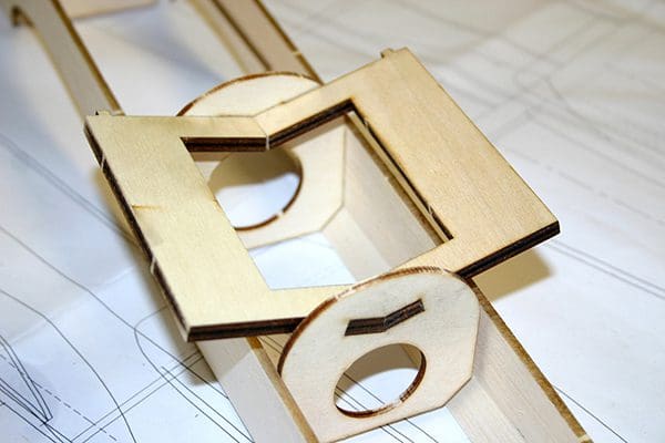
Engine Pods
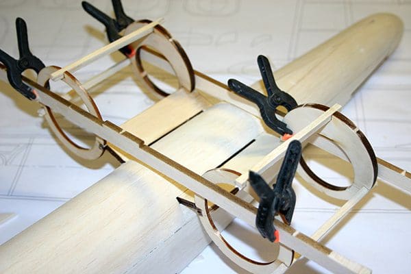
The engine pods can now be made up. Start by fitting N1 and N2 onto N3. Be sure to make up templates to achieve the correct angle of N2 and set square on N1. Refer to the Build Photos on the TND Ltd website for a visual explanation of getting the positioning of N1 and N2 correct. Add the 5mm sq. stringers to the circumference of N1 and N2. The pods can now be sheeted in soft 3.2mm balsa and the edges sanded flush against N1 and N2.
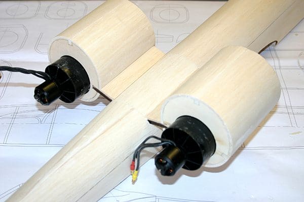
At this stage add the fan units, the speed controllers and wiring, and check they function correctly and rotate the correct way. The ESC can be secured to the inside of each pod with sticky backed Velcro. I used three dobs of hot glue to secure the fan. You don’t need anything more than that.
Now make up the small thrust tubes and slide these over the discharge outlet of each fan unit. On the plan is a cut outline of the thrust tube before it is rolled. The tube is made from 140-micron thick acetate. You will be able to source A4 sheets of this on eBay or from a stationery shop. It is basically the thin clear plastic used for report covers.
The easiest way to make the tube is to roll the end of the acetate around the fan unit as tight as you can make it. Then secure with a small piece of Scotch tape at the fan. Finally, run a piece of tape along the joint length. Use a couple of dobs of hot glue, one on the top and one on the bottom, to secure the thrust tube to the fan casing. Again, it doesn’t need any more glue than that!
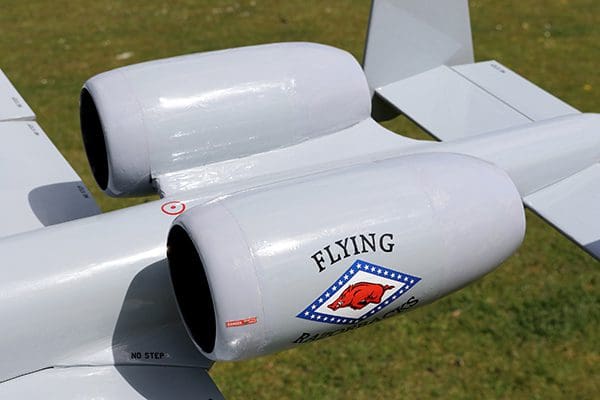
Take the vac formed rear pods and trim these so both the N4 support rings fit snuggly inside. Then open the ends to allow the tail pipe to sit centrally in the opening. Spend a little time getting this correct. The vac formed rear pods are a slightly smaller diameter than the main pod. This is so you can feather the edge of the balsa sheeting smoothly into the rear vac form mouldings. A similar process is applied when fitting the front nose of the engine pod.
The bottom fuselage battery access hatch can now be marked and cut out. To retain this hatch I made a Solarfilm hinge. To secure, I used one of the small brass spring catches from SLEC Ltd at the rear of the hatch, as shown on the plans.
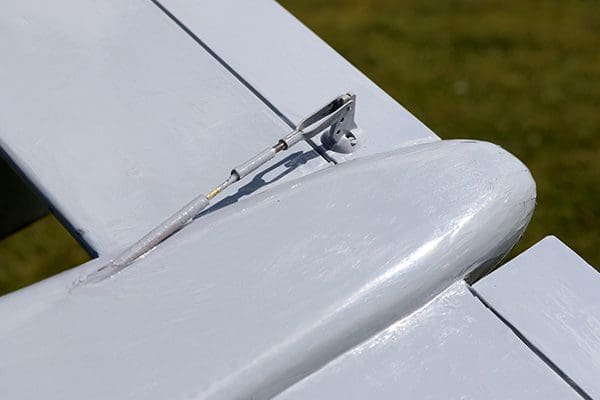
Fin & Tailplane
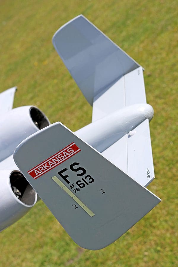
The tailplane and fins are made from 5mm medium/hard balsa.
Make up the two fins, then profile the leading and chamfer the trailing edges. Put the fins aside and only glue into position once the model is nearing completion.
Now make up the tailplane. There is a template outline shown on the plan, which you can use. Round off the tailplane leading edge and chamfer the elevator top and leading edge ready for the hinges to be fitted.
Make up the elevator torque rod and dry fit the tailplane and the elevators.
Wings
The wing is constructed in three sections, with a centre and two outer panels.
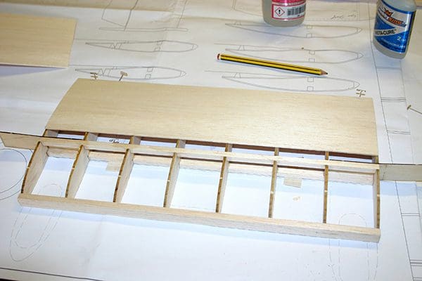
Construct the centre section first. Start by pinning the lower spar over the plan. This will have to be ‘chocked’ up slightly with some 2.4mm sheet packing. Then fit the six inner W1 wing ribs. Note the two outer ribs are split to allow for the continuation of WS1. All ribs should be positioned vertically using a set square.
Fit the top spar into position and glue the two wing braces WB1 at the ends. Use the two split W1 ribs and fit the front portion to the spar and WB1. The ribs should be positioned using a set square. Now fit the rear part of the outer W1 ribs, then fit the inner leading edge made from 3.2 mm sheet balsa, shaped to follow the contours of W1. The top skin of the wings can now be applied using 1.5mm sheet balsa.
Remove the centre section from the plan and construct the outer sections.
Again, starting by pinning the spar over the plan. The spar will require ‘chocking up’ slightly with some 1.6mm sheet packing at the position shown on the plan. Note that the top and bottom spars will also need notching to allow wing ribs W6, W7 and W8 to sit flush into the spars. Position the remaining wing ribs W2 through to W8. Now fit the top spar, followed by the inner leading edge and the aileron inset trailing edge between W3 and W7. Shape the leading and trailing edges ready for the balsa skinning to be applied.
Using the dihedral template trim the top spar overhangs at the location of W1 to take account of the wing dihedral. The wing panel can now be removed from the plan and the opposite panel now constructed to the same finish.
The outer wing panels can now be fixed to the centre section, checking that the correct (and matching) dihedral exists under each wing. Now re-pin the outer section back to the building board and sheet the top of the wing. Repeat the procedure with the other wing panel.
At this stage the aileron servo bearers can be cut and fitted. As an alternative you could use a proprietary plastic servo mount as supplied by SLEC or similar. These fit flush into the wing, with just the control arm showing and are very neat.
At this point install the aileron, ESC and power wiring through the wing. Now apply the shear webbing between the top and bottom main spars, as shown on the plan.
Sand the inner leading edges and trailing edges flush with the ribs on the underside of the wing, ready for sheeting. Remember to install the reinforcements around the wing dowel and the wing bolt.
Now skin the underside in sections, as done before, starting with the inner section first. You will, at this point, need to remove the jig tabs in order to complete the skinning.
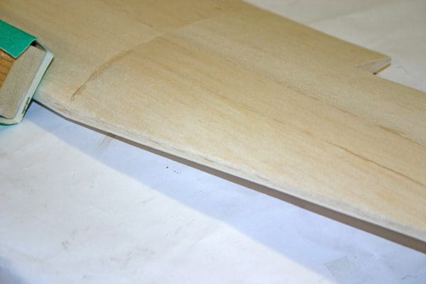
Trim the top and bottom wing skins flush with the leading and trailing edges. Cut and fit the outer leading edge from 6.5mm sheet balsa. Shape the leading edge to the nose profile as shown on the plan.
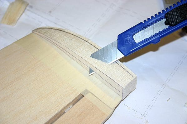
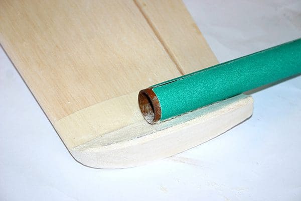
Cut out the wing tips to the profile shown using two pieces of 12.5 mm balsa sandwiched together to form the correct thickness. Glue these to W8. Roughly shape the tips on the outside surface, using a razor plane, then sand to a smooth flowing profile to match the wing.
The inside edges are a little trickier as they require ‘scalloping’ out to make that concave profile so reminiscent of Hornier wing tips. Have a look at the build photos on my website for a photo explanation.
Make up each individual aileron as shown on the plan. Start by cutting out the bottom skin to the exact dimensions of the aileron, then add the leading edge made from 6.5 mm balsa. Begin to add the riblets. Trim the top of the leading edge to match the rake angle of the riblets. At the aileron horn point insert a support block made from balsa. Finally, enclose the aileron with the top skin, trimmed to suit the opening in the wing.
To finish, use fine abrasive paper to round off the leading edge and smooth out any imperfections.
Wings pods
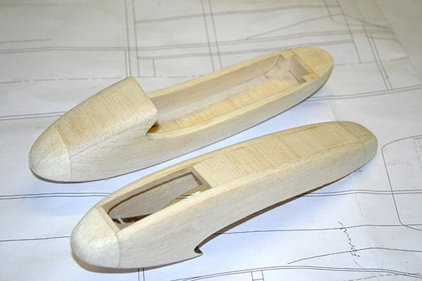
These are made up as detailed on the plan. Start with lining WP1 with the doubler WP2, making two pairs. Cut in the wheel support plates WP3. Add WP4 and 5 to one side of a pair and then enclose with the other side.
Sheet the top of the pods with 5mm scrap balsa from the CNC pack. Then cross sheet the bottom inside of the pod, leaving an opening for the 50mm wheels. Add the nose and tail block and shape to a smooth flowing curve. Finally, drill the axle holes and fit the wheels.
Glue the pods to the underside of the wing and use lightweight filler to blend the top sheeting smoothly back into the wing.
Putting together
Make up the wing fillets using the templates shown on the plan.
Glue into position FP1 and fit the wing dowel. Make the hole for the wing dowel in F5 and drill a 6mm hole for the wing bolt.
Now fit the tailplane. The rear tail block, which was shaped and removed earlier, will need a slot cut in to recess the elevator torque rod. When done the block can be re-glued back onto F8. Remember to grease the torque rod just in case it gets glue on it!
Covering
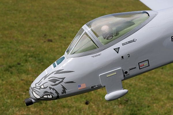
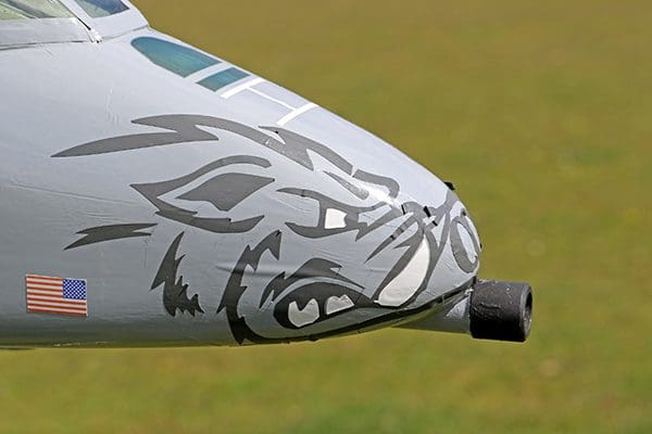
The prototype was covered using light grey Oracover from J Perkins. This is a good solid covering, and they provide a matching grey paint so the vac formed pods can be painted using it too. Finally, add the fins and finish the covering.
We are planning to have a full set of decals available for this model and these will become available at www.tonynijhuisdesigns.co.uk
Fit all the control surfaces with flat hinges and secure with glue. Fit all the servos and control horns etc.
On the prototype no ballast was required to achieve the correct C of G position with a 4S 4000mAh LiPo in the nose. Do be careful and mark the position of the battery as any slight variation will alter the C of G noticeably. The LiPo can be secured using self-adhesive Velcro attached to a battery plate made from scrap 3 mm lite-ply.
The canopy can either be fitted before or after covering. I prefer to detail the cockpit, fit the canopy and then cover the model around the canopy. But it’s up to you.
Flying
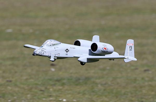
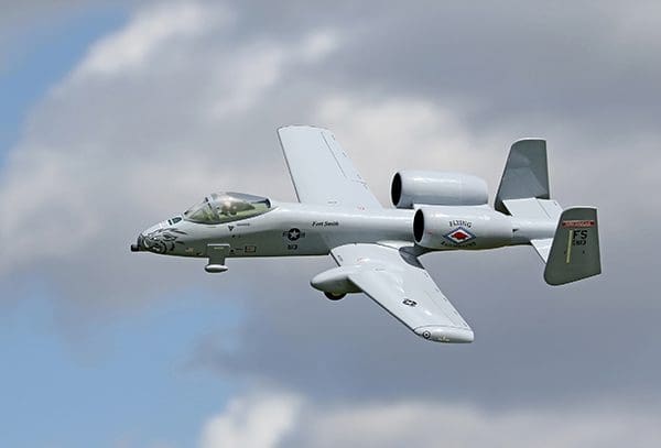
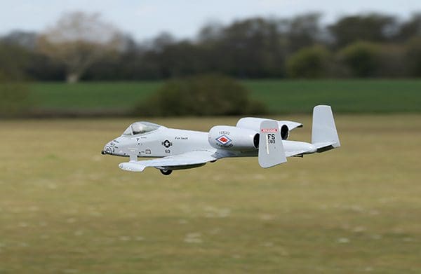
As I mentioned earlier the model will ROG very easily so there is no worry concerning taking off. Pointing the model into wind and gradually opening the throttle to full, the A-10 will accelerate smartly. There may be a slight tug to the left on acceleration so always sit the model some 10 degrees to the right of the take off run.
Within 20 metres apply some up elevator and she’ll be climbing away with gusto. As soon as your A-10 has cleared the ground you can easily throttle back to two thirds power. You will find that full throttle is not really required other than for take off and fast climbs. Once the initial climb out has been executed and the model is fully trimmed out, she will fly ‘hands off’ at around half throttle.
You’ll find the Thunderbolt is very stable and flies on rails, especially on a calm day. However, if you fly on a windy day the model will be thrown around a little so be prepared to fly with a little more throttle.
The A-10 was designed as a low-level strike/attack aircraft so going in a straight line, fast and low, and then pulling up into a wing over is what it was designed to do! The model will exhibit the same characteristics as the full size. Watch a few YouTube clips of the real thing and apply that to your flying routine. Just remember to keep the routine smooth and keep the momentum going into the manoeuvres. The little 4S 11-bladed FMS fan units do give an amazing punch, so you can expect a near vertical climb if you have some momentum going into it.
Landings are very straightforward and generally you will run out of elevator control before the model will stall – those Hornier tips really do work very well! Keep the power on during landing approaches to avoid any pitch change when powering off. If you do land without power there are no surprises, but she is quite slippery through the air.
Don’t be tempted to adjust the C of G. The model has been thoroughly tested and where it is shown on the plan is exactly where it needs to be! Flight times are surprisingly good, so expect a good six to eight minutes, depending on throttle use.
The A10 is one of my favourite aircraft and since the prototype was designed and built some two years ago it has become my all-weather hack. It is so easy to operate with no undercarriage to worry about, has great duration and looks fabulous in the air.
All I can say is I’ll guarantee you will enjoy the flying experience and the quirky nature of this great looking model. So build one and enjoy!
Datafile
Name: A-10 Thunderbolt II
Model type: Twin EDF mini jet
Designed by: Tony Nijhuis
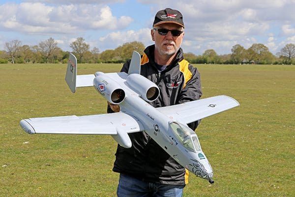
Wingspan: 40” (1067mm)
Fuselage length: 38” (962mm)
Wing area: 1.72 sq.ft. (0.16 sq.m)
All-up weight: 48oz (1.3kg)
Wing loading: 31oz/sq.ft. (9.86kg/sq.m)
Parts, packs and further help
A vac-form set, combined CNC/wood pack and decal set are available from Tony Nijhuis Designs Ltd (TND), as are additional copies of the plan.
Website: www.tonynijhuisdesigns.co.uk
Email: [email protected]
Phone: 07563 518159 (9am to 4pm)
Finally, the forum at RCM&E’s web home – modelflying.co.uk – is a great way to chat with other builders and see their photos.