Fast and furious… no, that doesn't describe the model, merely the way this design went from drawing board to RCM&E free plan. Heres the scene: Friday, five o'clock, and our esteemed editor calls in a panic. Due to unforeseen circumstances (!) we need a free plan for the next issue – any ideas? Unfortunately, the only model which would have been suitable had just been sold at the Hastings 2002 Model Airshow.
Oh, no! came the reply, we only have three weeks – what do you reckon 'Tone, could you build another one? We need some studio pictures… and, of course, some flying shots… oh and by the way, don't forget the plan and the article!
By this time, my train from Charing Cross was beckoning (yes, I do have a day job you know), so I agreed to think about it. Anyway, before leaving the office I thought I'd just check to see what shape the CAD plan was in; as it happened, everything was fairly complete, so I took a print-off to have a good look when I got home.
Moving forward to 7.30pm that Friday evening, I got to thinking about the possibilities. If, say, I could manage to build and finish the model before Sunday our Ed, who was coming to the Hastings Festival of Flight armed with his camera, could photograph it in action to supplement the studio shots. Hey, now that seemed like a challenge I just couldn't resist! On the stroke of 8.00pm, I started cutting balsa wood; six-and-a-half hours later – the air thick with dust and cyano fumes, the floor knee deep in shavings – my model was finished, and ready for covering.
Pleased with my progress so far, on the Saturday I thought Id take it easy, so I didn't start the covering until 4.00pm. Again, a bit of a marathon session saw the airframe completed, including graphics, ready for its first outing. The time was 11.00pm (oh good, an early night).
MOTORING ON
Well, that's how the model came together in record time. Did it fly on Sunday? You bet it did, and in the very capable hands of young Ali Mashinchy, who put the Aerovan well and truly through its paces. More about that later.
Some 15 years ago, I made a similar model built around the Union 270 motor and gearbox, pulled from a brace of polystyrene Cessnas; cant remember the manufacturer, but they constituted one of the first ARTF electric models on the market – quite a revelation in the late eighties.
The wing span of this early Aerovan was 72 and, as I remember, it only had a rudder and elevator. Performance was as you might expect, tame, and a bit like a powered glider. Although enjoyable and pretty in the air, it wasn't very exciting, and soon got put in the loft and forgotten. About two years ago though, off came the proverbial mothballs – time to pull her out of the loft, whereupon she was re-packed with the latest generation of cells.
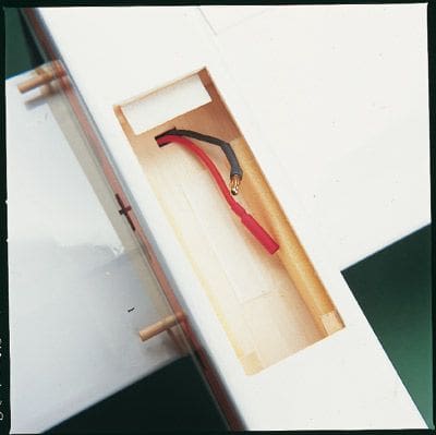 Battery access need not be a problem on the Aerovan thanks to a handy underside hatch.
Article continues below…
Enjoy more RCM&E Magazine reading every month.
Click here to subscribe & save.
Needless to say, performance was more lively, but the design was dated and needed the sparkle expected in todays world of electric whiz-bangs. So, Aerovan Mk.2 was drawn up, this being a clipped-wing version sporting a fully symmetrical wing with ailerons, and fitted with a pair of direct-drive Speed 400 6V motors. How did it compare with the Mk.1? It didn't. This model was fast, aerobatic, and pretty to look at. As a consequence, it had quite a few outings in the 2000 flying season. Unfortunately, with other designs snatching the limelight last year, it got pushed to the dusty corner of my workshop, but I'd already earmarked the Aerovan as a possible future plan or kit.
Okay, that's the background – now on with the building. No, I don't expect you to build and fly one in a weekend! However, if nothing else, my experience does prove that this model is quick to assemble, despite using the traditional built-up wing construction.
FUSELAGE
Start by cutting the fuselage sides and all relevant formers from 3.2mm (1/8) balsa. Line the fuselage side edges with 6.5mm (1/4) square soft balsa longerons, as indicated on the plan – and make sure you produce a right and left-hand panel! Next, fit the fuselage formers 2, 3, and 4, then make up the battery compartment with parts 5 and 6. Fit the remaining fuselage side into position, checking the alignment before securing with your chosen glue.
Before pulling the rear permanently together, feather the 6mm square longerons so that overall width at the tail is 12mm (1/2) when complete. With this dimension achieved, glue them together and fit the tail block.
Add the remaining former, number 7, at the nose. Note: You may need to put some saw cuts into the 6mm square longerons to aid pulling the nose onto former 7. Following that, cut (from 6mm sheet) and fit the cockpit floor (8). Now begin to cross sheet both the open upper and lower surface of the fuselage with 2.3mm (3/32) balsa; trim any cross-sheet overhang to make it flush with the fuselage sides, and fit the wing seat doublers (9), having cut them from 4.5mm (3/16) balsa.
Make up the four nose pieces, i.e. two No. 10 and two No. 11, from 12mm balsa.
Glue the side pieces on first, at an angle, allowing them to overhang the fuselage sides by 3mm. Fit the top and bottom pieces, then add a further piece of 12mm scrap to cover the opening left at the front of the nose; that done, you can begin to razor-plane and sand the parts to form a smooth, flowing curve into the contours of the fuselage.
Article continues below…
From sheet or a solid, rectangular block, cut a cockpit. Trim to match the plan-view shown, and then the side-view; next, plane away enough material to make the front two windows rake back. Once happy, glue the cockpit block into position, and feather it to the surrounding fuselage.
Give the whole a final rub down with sandpaper.
To finish this stage, cut holes for the wing dowels, make and fit the servo mounts, then cut out the radio access hatch. The back of the hatch was laminated using 2.3mm balsa, with the grain running in the opposing direction to create a ply strength finish. Details on securing are shown on the plan.
The tailplane and fin parts, 12 through to 17, are cut from 3.2mm firm sheet balsa and are covered and fitted separately.
WINGS
Article continues below…
There are three types of ribs youll have to fashion. As there's only a slight variation between them, remember – as you cut – to number each one directly after you finish. On my prototype, the inner trailing edge (i.t.e.) and leading edges (l.e.s) were cut from 6mm and 9.5mm sheet balsa, and shaped, only once the wing skin and cap strips had been applied.
Firstly, pin the 3.2mm square spruce lower wing spar over the plan and do likewise with the i.t.e., making sure its raised off the paper using lengths of 3.2mm packing at regular intervals. Fit the wing ribs, and decide whether you wish to add dihedral. For models with rudder as well as aileron and elevator, Id say leave it out since the addition of rudder will help in the turns, and youll have a more agile model overall. On the other hand, should you choose the aileron / elevator only approach, I would suggest building in dihedral to hold the model better in the turn, whilst increasing stability.
Fit the top wing spar, and the l.e. Now remove the wing panel, and fit the l.e. upper sheeting, using 1.6mm (1/16) balsa.
At this point, feed the motor wiring through your wing, running each lead to the nacelles. Sheet the upper and lower surfaces at the root, fit cap strips over the upper rear section of each wing rib, and then trim both l.e. and i.t.e. Sand the wing smooth.
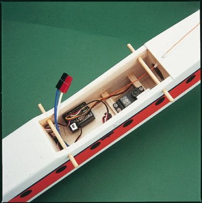 Not massive but neat. There's room for elevator and rudder servos although I didn't fit the latter.
Add shear webbing pieces, using 1.6mm sheet balsa, which can be placed between the top and bottom main spars (as indicated on the plan). Make up the aileron torque rod, and secure it between the fixed part of the t.e. and i.t.e. at the wing root. Produce some ailerons, install the hinges, and test fit each unit. Finally, fit the wing tip, which is made from 12mm sheet balsa. Then, simply repeat all the above to make your other panel.
SHAKE AND VAC
Cut and fit the nacelle plates (18), and feed the motor wiring through. Then, sheet the underside of the wing around each nacelle. Trim said vac-formed nacelles (available from Nexus – see datafile), and screw-fit these to the mounting plate (18). Cut the top edge of the plastic flush, and add the top plate (19), noting that the latter overhangs the edge of 18 by a millimetre or so. This makes it sit flush with the vacuum formed moulding. Finally, profile the edges of 19 to a smooth curve with sandpaper.
Join the wings using fibreglass tape, and secure using either PVA glue or resin. Cut a pair of slots, and fit the two aileron servo mounting plates in the position shown on the plan.
COVERING & FINISHING
Article continues below…
The prototype was covered in white Solarfilm, whilst Solartrim is used for the coloured graphics. That done, a few last jobs can be effected…
Trim the nacelles to allow each motor shaft to exit, and cut some cooling holes as well.
Solder the wire ends to each motor, remembering to fit the suppressor capacitors (if supplied) as you go. To secure the motors in their nacelles, use either epoxy or double-sided servo tape – both methods work equally well. Now, fit the Gunther props, and refit your nacelles to the wing.
Both tailplane and fin can now be glued to the model, and the elevator / rudder fitted. Add the control horns, and fabricate some pushrods in the traditional way. The prototype model has lengths of 16 swg piano wire, with a Z bend at one end and a nipple link at the other. Very simple and effective, due to the relatively short run between servo and control surface.
Put your servos in the fuselage and wing, then make up the aileron pushrods from two 8 long, 2mm threaded rods. Secure the receiver and 30 amp speed controller with Velcro, added as appropriate in the fuselage. Make a set of end connectors, as these will allow the wing wiring to be easily unplugged from your speed controller.
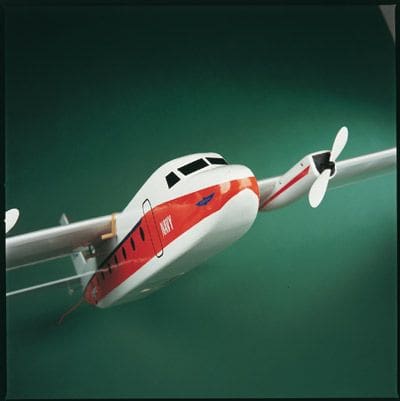
 You'll find the Aerovan to be amazingly aerobatic
FLIGHT LINES
So, there we were – the Hastings Festival of Flight had just finished, and a burst of late summer sun made a perfect end to the day. All we needed were some sparkling flying shots for the magazine and our Ed could take the model away for its studio session.
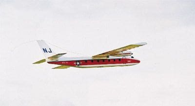
To ensure wed achieve some sparkling photos, we needed a sparkling pilot – enter the young Ali Mashinchy. Needless to say, Ali soon got the hang of it, and let slip that he thought it better than the Twin Star… Great, because that was the idea! Loops, bunts and wing-overs, inverted flying and stall turns can be achieved, even without rudder! that's what its capable of in the hands of an expert. But whats it like for us mortals?
Well, I'm no Ali, but the model does feel very comfortable and responsive, like an old hack that allows you to push the boundaries without fear of any biting. Surprisingly, Aerovan still retains its ability to soar; a couple of times when bored with the whiz-bang flying, I climbed and managed to hunt a few thermals, which stretched the flight to 15 minutes.
This model really does have a bit of everything going for it. Needless to say, if you lose power, the model will revert to its glider properties, i.e. a long, flat glide angle, with little worry of a tip stall if you slow her up. Basically, a good fun all rounder.
DATAFILE
Name: Aerovan
Model type: Twin engine transport
Designed by: Tony Nijhuis
Wingspan: 571/2
Wing chord: 73/4
Wing area: 446 sq. in
Fuselage length: 423/4
Recd power: Permax 400 6V x 2
Recd propeller: Standard Gunther
Recd no. channels: 3 / 4
Control functions: Aileron, elevator, throttle, rudder (optional).
Nacelles: Available from the RCM&E Plans Service, priced at £7.95 (including UK p&p) for the pair.
Click here to go there.
-
Got a question? Click here to go to the Tony Nijhuis plan builders forum section.
-
Click here to order the Aerovan plan.


