
Dave Batchelor finishes and flies his 98″ Vulcan V-bomber built from the Tony Nijhuis plan.
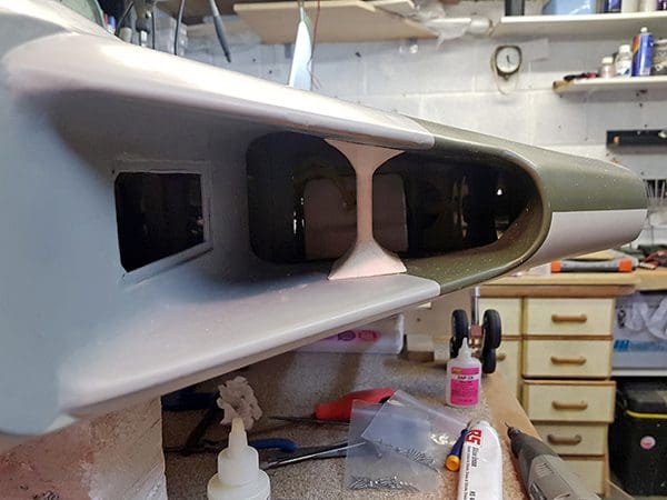
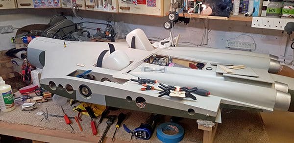
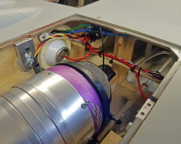
Running fuel lines and wiring in the fuselage was going to be very untidy as only the holes in the ribs and bulkheads could be used to run them through. Good visibility inside is afforded by the large air intakes so I wanted it to look good inside as well as out.
I used 1/4″ dowel from the front to the engine bay on each side to carry wires one side and fuel lines the other, and more dowels side to side to carry the wiring and air lines to the two sides, fixed with either cable ties or Velcro straps.
Enjoy more RCM&E Magazine reading every month.
Click here to subscribe & save.
The inner frame, under the removable nose, to hold the electrics, was made of ply and made as long as possible to get maximum weight at the front where it is needed to balance the heavy turbine and thrust tube. The frame holds the fuel pump, gear/brake valve and turbine battery on one side, with the receiver, gyro, remote receiver and two radio batteries on the other side.
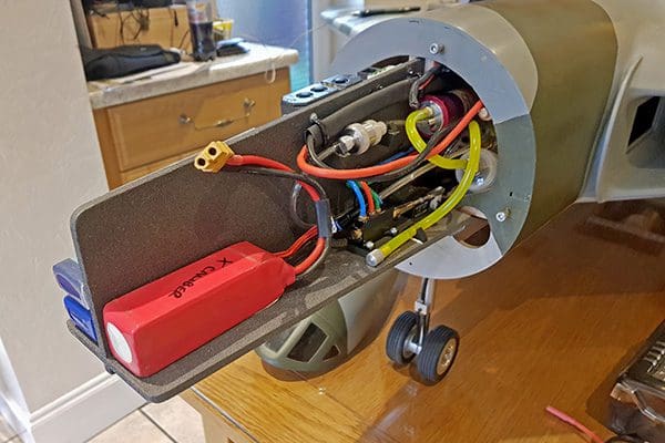
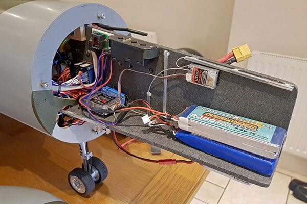
The electronic gear door sequencer and the lighting control PCB is mounted on the underside of the front extension, along with the lighting battery. The radio batteries were sized to correct the C of G.
Balance By Spreadsheet
Finding the C of G on such a large model was going to be difficult. I was discussing this with my friend, Andy and he said that it should be possible to write an Excel spreadsheet to do this. In no time at all his wife Teresa had worked out the math and Andy wrote a spreadsheet, which not only worked out the longitudinal C of G but also the lateral C of G.
Using this, and my wife’s kitchen scales, gave me the weight of batteries required to put the C of G where it is supposed to be. Subsequent verification by lifting the model on two points under the wings proved it to be completely accurate and flight testing also showed it to be fine. Well done and thanks to Teresa and Andy!
Light Up
There are two lots of lighting on the model – landing lights and dummy afterburners. The landing lights use LED lamps from car reversing light bulbs. The retracting mechanism is home-made, and the lamps pop out of the wing using a micro servo.
The afterburners are red LED lamps from car stop lights. The lamps are controlled by a pair of programmable Mosfet switches made by Pololu. These can be programmed to switch at a certain point on a proportional R/C channel. One circuit for the afterburners runs off the throttle channel and the landing lights have their own channel so they can be switched on at will.
Cover Up
The model was covered with fibreglass using one layer of 28g/m cloth on the top and one layer of 44g/m cloth on the underside. It was the first time I had ever fibre glassed anything and so I started with the rudder. The first side went quite well but I was disappointed to find that it was not all glossy when it dried. I then found out that it is not supposed to be, and the resin should only fill half of the cloth weave. I really should have paid more attention to the tutorials online!
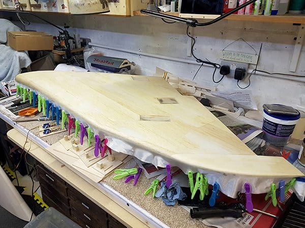
A lot of rubbing down later and I covered the other side correctly, removing any excess liquid before it dried – much better. I then used Z Poxy skinning resin for the final coat, applying it with a very soft, thin and wide paint brush. It dried without brush marks beautifully. Doing the fuselage and wings was bit of a bigger job but overall it was not the nightmare I was anticipating.
After a coat of primer was applied, I could see just how bad the surface finish was! Lots of rubbing down, followed by more filler primer and more rubbing down had it taking shape. I used 3M Acryl-red glazing putty, which dried quickly and could be easily rubbed down to produce a very nice surface.
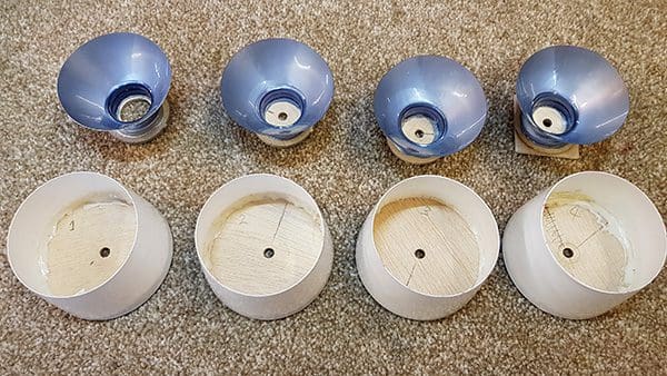
Mouldings
The cabin and the dummy engines are supplied as vac mouldings, but the large underside dummy engine mouldings were done in two halves, so a joint was going to be visible. Vulcan co-builder, John Rands had given up trying to make a nice job of his and in the end he set about making a mould from which he produced four nice glass fibre engine casings. He kindly lent me the mould and I made four for myself.
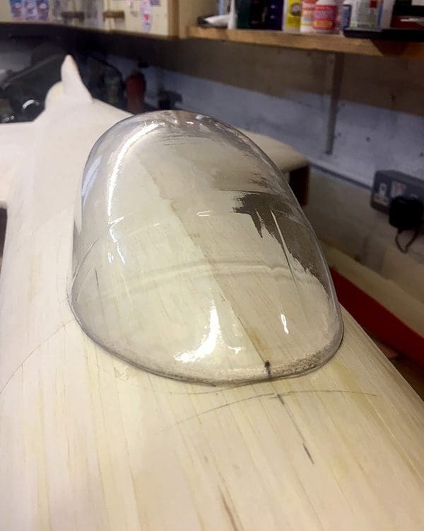
I later repaid him by making a mould for the bomb aimer’s window ‘bulge’ on the underside of the nose section, which worked out well and I lent him the mould to make his.
One thing I had not allowed for when deciding where to break the fuselage for my removable front was the location of the cabin moulding. This, it turned out, was almost half on each side of the break; it was going to take some figuring out! It sits on the fuselage just as it turns down towards the front, so I had to deal with fitting a very thin vac moulding to a surface with compound curves, which also had to be removable.
I first made a base by soaking 3mm balsa sheet and strapping it to the fuselage. Several re-soaking and strapping sessions were required, leaving it to dry completely in between and resulted in a nicely shaped piece that fitted perfectly. I then had to cut this to go inside the cabin moulding, knowing that if I took too much off I would be doing it all again.
Once they fitted together, I made some internal formers to support the moulding and the result was a very strong cabin that fitted the fuselage well. As the cabin is a sealed ‘bubble’ it is likely to be affected by the sun, so holes were drilled prior to finally fitting the cover so that all areas of the cabin are vented and won’t blow up in the sunshine. Now I just had to make a removable mounting system for it…
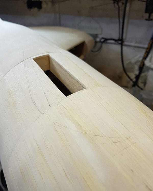
An idea came to me to use a block glued to the underside, which could be lowered into a slot in the top of the nose cone just to one side of the central former. A box was made in the front cover around the slot, resulting in a firm fixing of the cabin. But how to stop it popping out?
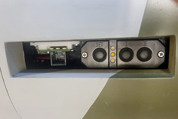
I had planned a refuelling probe in the nose and decided to make this into the final securing pin for the cabin. A piece of thin piano wire was fitted to the inner sliding piece of the probe, which slides in a piece of ‘snake’ inner up to the cabin area and goes into a hole to hold the cabin down. I later found that the PowerBox sensor switch and the turbine I/O board could be fitted below the slot, allowing fast access to the on/off switch by simply removing the cabin.
All the servo extension leads were made using PowerBox twisted cable and terminals so that each one is exactly the length required. If you have the correct crimping tool and take your time it is not half as difficult as it seems to make servo extension leads. Every connection can be scrutinised and ‘tugged’ to be sure it is good before fitting the shell.
Colour Scheme
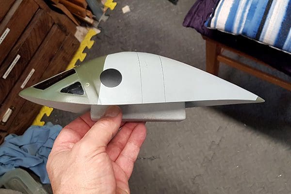
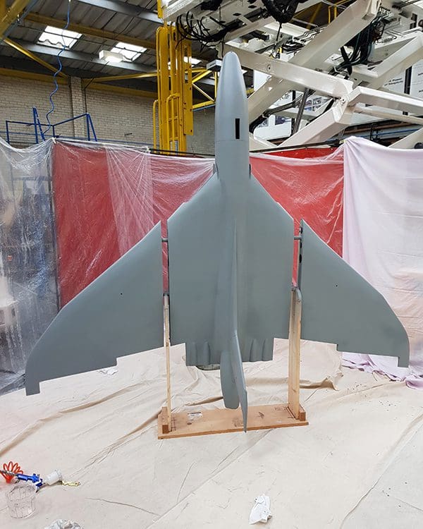
The time for painting was fast approaching. I had decided that I wanted a camouflage scheme rather than the anti-flash white, but with a grey underside to aid orientation from a distance. The restored XH558 is probably the easiest full size to model as so many photos and so much information is easily available, but she has the wrap around camouflage scheme, so I looked elsewhere.
The Vulcan based at Hendon RAF museum was almost chosen but sadly she is nosed into the corner of the bomber hall at Hendon, looking very sorry for herself. It also meant that good all-round views were difficult to get.
I settled on XJ824, which is based in the large hanger at Duxford. She was stored outside for many years so there are many unrestricted photos of her on the internet and now she is inside so you can walk around her and also get good views from the gallery.
Modelling XJ824 meant a lot of bespoke decals were needed and Nigel Wagstaff at Flightline Graphics did a fine job of creating them. Luckily, he had to go to Duxford for something else and took the necessary photos for me while he was there. I used the same paint codes as Duxford had, using BS627 for the underside, BS637 for the top and BS241 for the green.
The underside was painted first, followed by the top grey. I made a frame to support the aircraft on the main wing tubes (wings partially fitted, leaving a gap) and this meant that the airframe could be rotated 180 degrees to do the underside and the top at various angles as required. The paints were from Avenue Coatings in Colnbrook near Heathrow, who not only mixed the colours but were able to supply aerosol ‘rattle’ cans from my mix of paint for touch up purposes.
Masking for the green took a time! It might look random, but most Vulcans have close to the same green markings, so armed with a suitable plan photo and having worked out the scale and several base points, I started to plot out the position of the green sections as close as I could. I started with 3M 3mm wide masking tape, which was able to go around the curves very well.
With the shapes plotted out in tape, I then used wider tape and paper to cover the airframe. I did half at a time, with one wing on, which was just do-able in the workshop. Once sprayed the tape was carefully removed with the paint still wet. I let the paint dry hard for a week before turning it and doing the other half.
Radio Check
I took the model to Motors and Rotors for Dave Wilshere to case his eye over and check the set-up of the radio. All was fine, except Dave noticed that there was a slight twist in the fin! He had flown another TN Vulcan and this one had an even worse twist in the fin. I do not know how it was not noticed before and Dave said it was only slight and would fly okay, but once you see something like that you always know it’s there. I had to fix it even if it meant making a new fin.
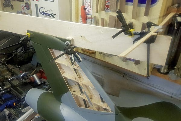
By removing the wood from one side and cutting around the carbon tubes going up through each rib, I was able to take out the twist by clamping it in the correct position to an adjacent shelf and applying glue around the tubes and ribs. When it had dried, it stayed in the right place and all (!) I had to do was re-skin, glass and paint it. It set me back weeks, but I know it is right now.
The decals were fitted and needed fixing and protecting. I did a lot of research and bought a lot of different spray coatings. The decals supplied by Flightline graphics were very complete and there were going to be several on the underside that I would not be using, so I used them for testing the clear coats.
Most of them affected the decals badly and I almost gave up hope of finding something when I came across Hammerite clear matt spray. It worked a treat, covering the paint without marks, and it didn’t affect the decals – or so I thought. Small decals could be sprayed over and were not affected. But when I did some larger decals they started to crinkle! The solution is to use Tamiya X22 clear gloss over the decals, applied by brush, and then spray them with clear matt to leave a matt finish and undamaged decals.
The roundels and tail colours were all airbrushed using paint masks supplied with the decals by Flightline and blue and red paint from Avenue Coatings – FPF3 (bus red) and RAL9003 Blue.
First Flights
The model was taken to Phoenix MAC, where the turbine was run up and adjusted. All looked good and the surface of the model at the rear showed no signs of getting hot. I did not take the wings that day just in case I was tempted to fly it!
A jet day was planned at Sculthorpe in Norfolk, so with much trepidation the model was loaded into the van and I set off. The weather was perfect, with a breeze blowing but not too bad. The model was assembled and fuelled up. A small problem was noted with the gyro and as it would not respond to tinkering with the decision was made to bypass the gyro for the maiden flight.
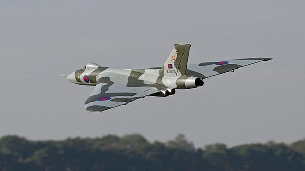
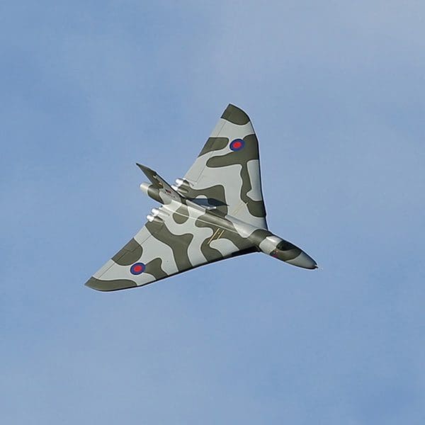
The engine was started and Dave Wilshire, who had kindly agreed to test fly the Vulcan for me, taxied her out. The model lifted off very smartly, flew superbly and looked wonderful, despite having no gear doors or belly markings. Dave landed and taxied back in, proclaiming it to be a success.
After a good check over and refuelling I took it up for a flight myself and with a pounding heart had a very pleasant six-minute flight. Landing was as uneventful as the flight itself and I had a beaming smile as I taxied back in. They were the only two flights that day for the Vulcan as I wanted to give it a good check over on the bench.
The only problems found were one of the main gear bogies had loosened a spring slightly, resulting in the bogies not hanging together straight on landing approach, something I only noticed in the photos afterwards. The gyro problem was resolved, and the system was reinstated.
Post Flight Tweaks
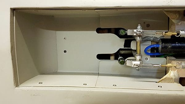
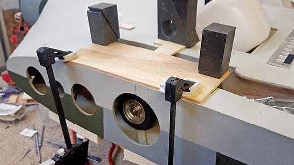
Since the maiden flight, I have fitted gear doors, each one fitted with a micro servo controlled by an SC-271 electronic sequencer made by the Hando Computer company and available on eBay for $14. It’s a really simple device, programmed from a laptop, and seems to work great.
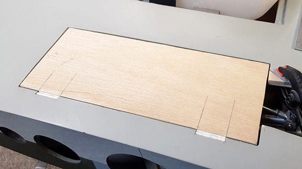
The main gear doors have a compound curve to them so 3mm ply was soaked and then clamped in place to the shape of the fuselage and left to dry. Afterwards they fitted in place perfectly.
There are small doors behind the main bogies, opened and closed by the legs themselves. The linkage for this took some working out! After the first couple of landings I found that the main oleos, when fully compressed on landing, allowed the rear bogie wheels to just touch the doors, causing some damage. I ended up shortening the small doors to clear the wheels (as I should have done in the first place!) and extending the main gear doors, with all the re-covering and painting that entailed. Nothing is easy you know!
As I mentioned earlier, I also made a bomb aimer’s ‘bulge’. The moulding process was not as bad as I thought and I soon had a new bomb aimer’s window taken from the mould. The mould has now gone off to at least two other Vulcan builders in the UK.
I also finished the underside markings, panel lines etc., which are so clearly visible when flying. The panel lines were all drawn on by hand with a pencil and then covered with the clear matt spray to protect them.
The final two pieces I made were radio aerials that go on the top of the fuselage; very delicate, so both are removable for transport.
Delta Delight
The four wing control surfaces are supposed to be set up with the outers as elevons and the inners purely as elevators. This caused some set up oddities with the gyro and I decided in the end to set the entire wing up as a normal delta. This simplified the set up as all four servos now went via the gyro.
The JMA (Jet Modellers Association) season opener/AGM was held at the BMFA site in the Midlands. Apart from an excellent facility, they have a very nice grass field. This time the gyro was in and working. It flew even better and the gyro totally locks it in like it is on rails. The full elevons meant the control throws could be reduced and adjustment via the transmitter was much more straightforward.
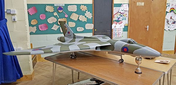
As a member of St Albans MAC, I was very proud to receive the Basil Dodds ‘Best New Model’ trophy at the club’s ‘New Models’ night for the Vulcan in early 2019.
I would like to thank John Rands for his assistance and for sharing some of his solutions and also to Dave Wilshire for his invaluable advice during the build and for carrying out the maiden flight for me.


