
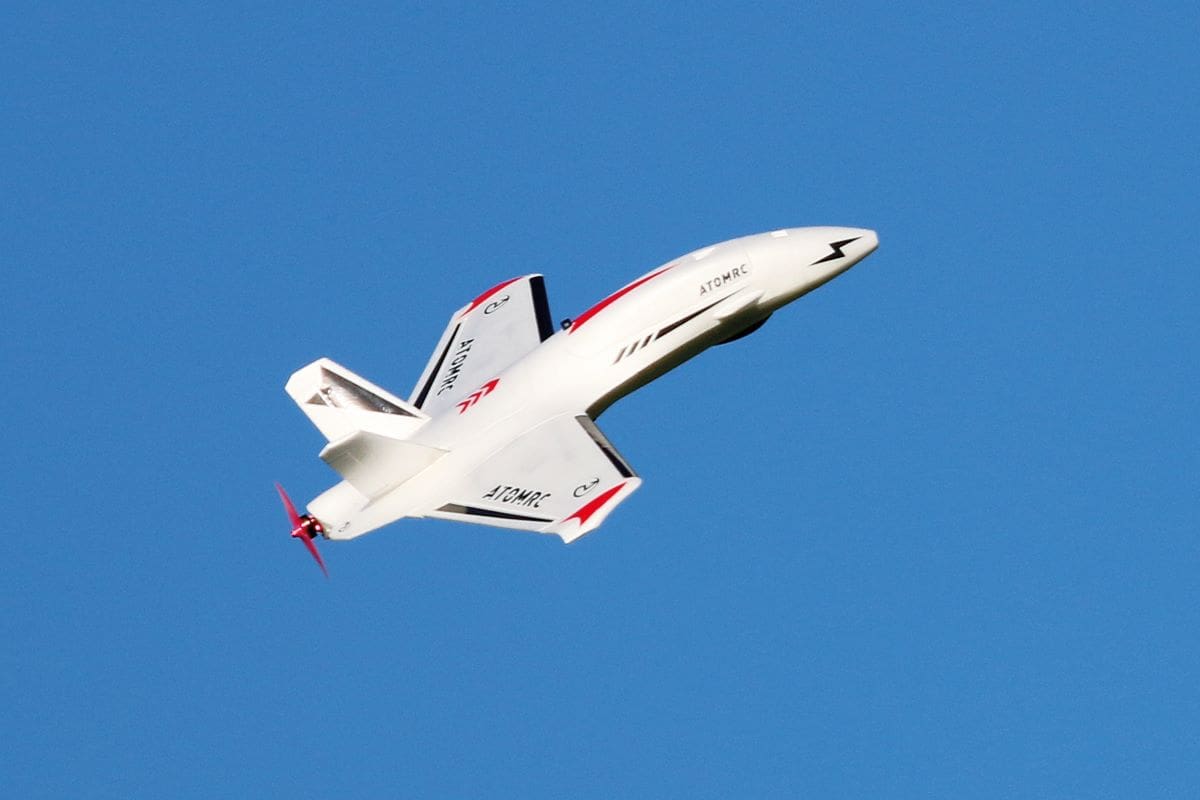
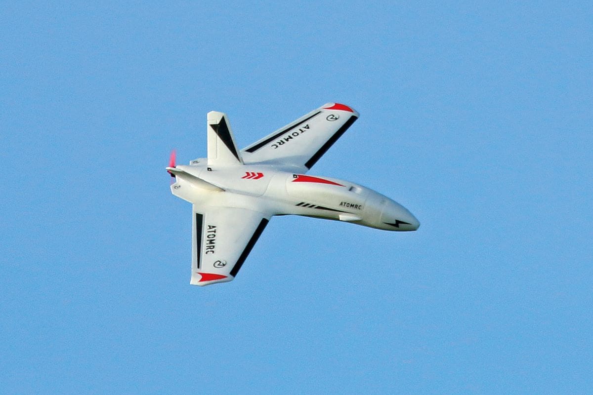
John Freeman assembles a multi-role pusher plane capable of camera toting, FPV or just good old sports flying!
words » John Freeman
photos » John Freeman, Kevin Crozier, Steve Hannon
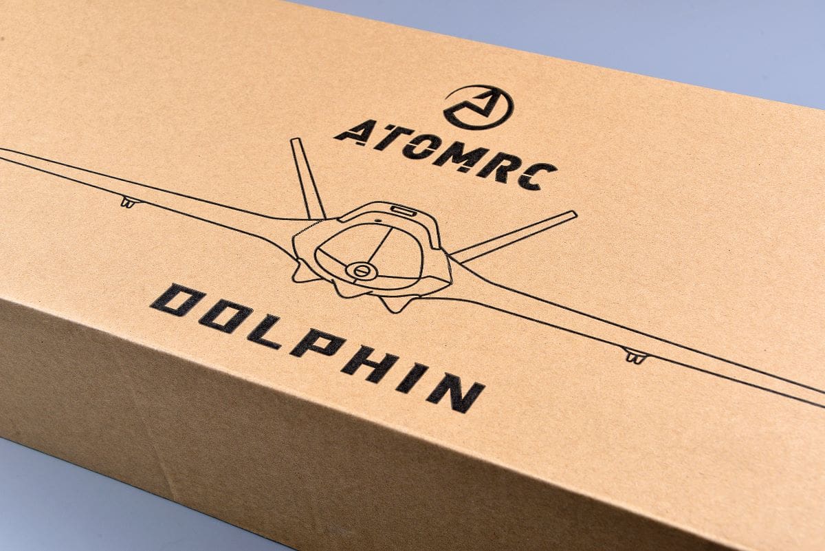
Our ATOMRC Dolphin kit was supplied by Neil Jones of www.flightech.co.uk for review. Although FPV ready, Neil is selling this model as a small, fun aerobat, which is perfect for throwing in the back of the car as a break from his customers’ more usual competition standard gliders. It’s just the thing for a quick flight whilst recharging the batteries for your bigger models.
Enjoy more RCM&E Magazine reading every month.
Click here to subscribe & save.
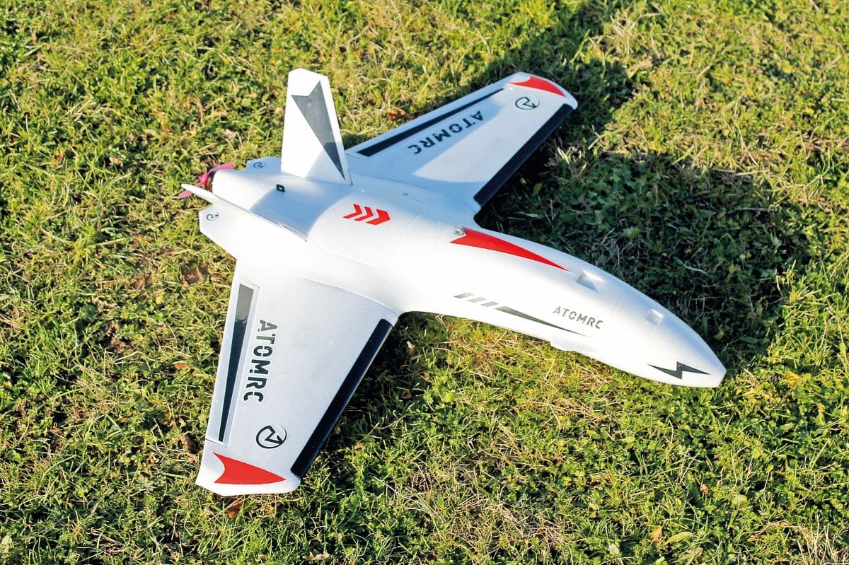
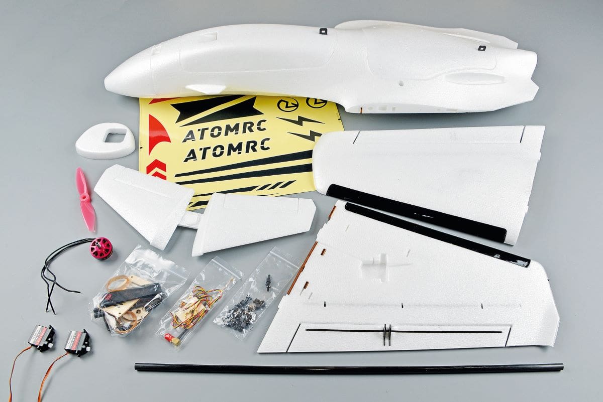
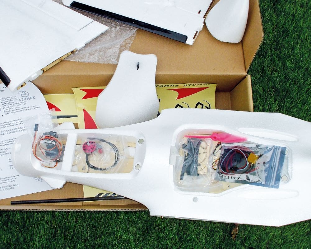
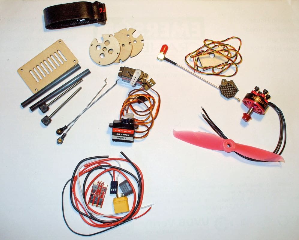
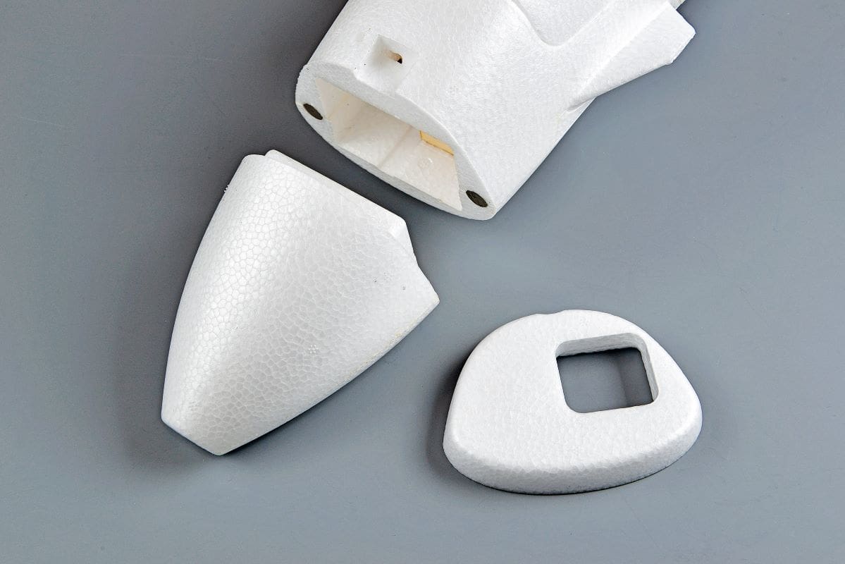
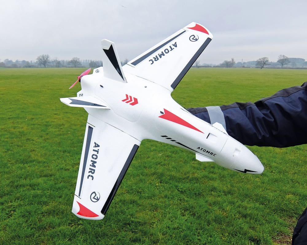
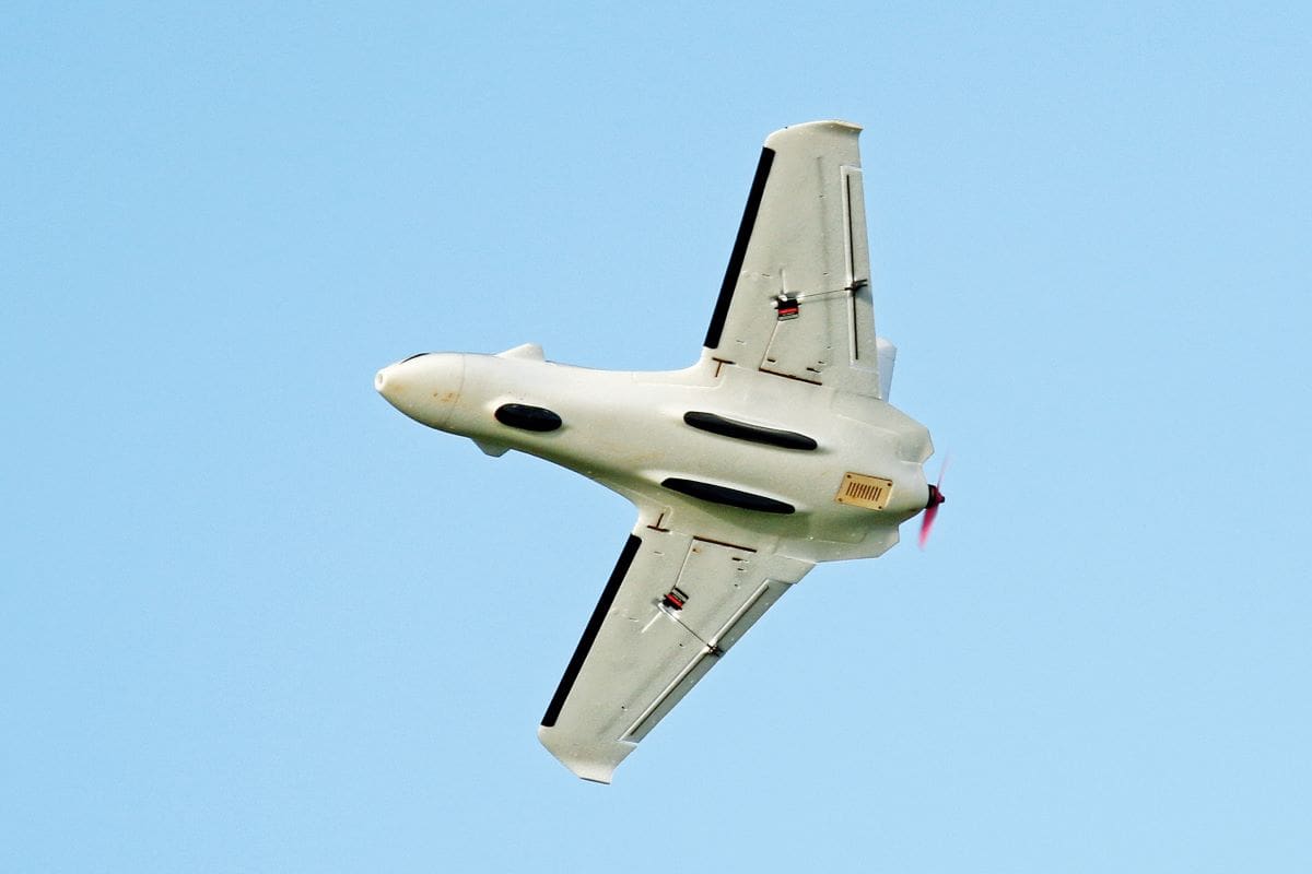
On opening the box, the first thing you see is the large fuselage and the short stubby wings, all moulded in extremely strong EPP foam. Two nose cones are provided, one for a GoPro and the other for the standard nose. All of the small items needed to build the Dolphin are located in bags stored under the two very large hatches, which are held in place with strong magnets.
A BIT OF WORK TO DO
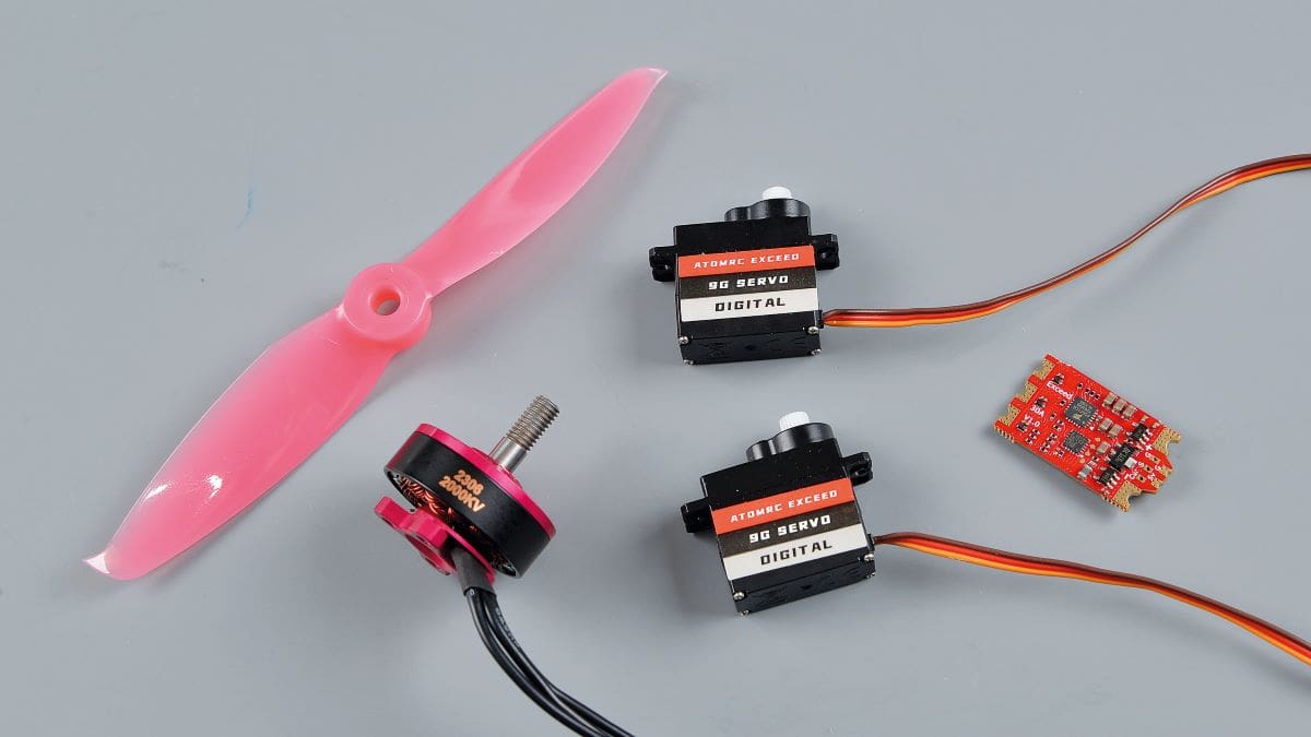
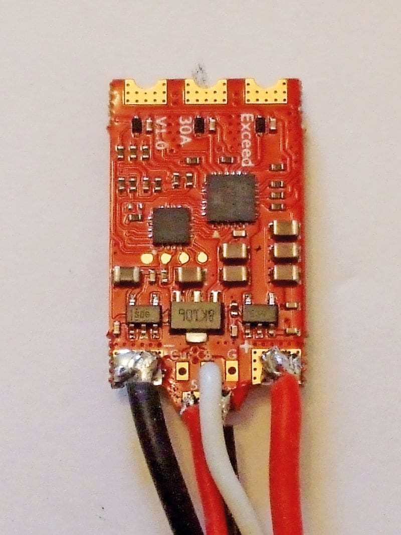
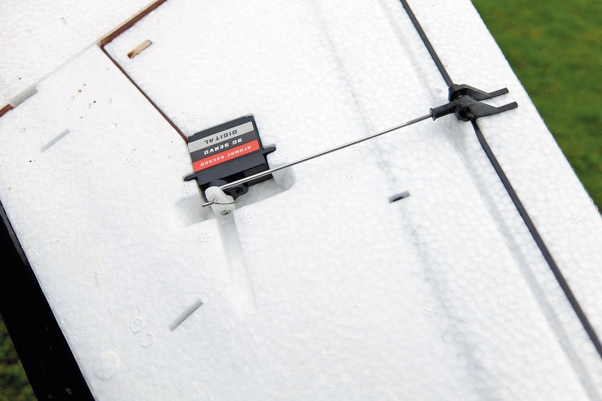
This model is classed as the pre-built ‘Plug ‘N’ Play’ version – just add the radio gear, battery and receiver and it’s ready to go. This is definitely written tongue in cheek as the ATOMRC Exceed 30A BLS 5V/3A BEC speed controller supplied requires all its wires to be soldered to the board. Also supplied is a 2306 brushless motor and prop, plus two ATOMRC Exceed 9g servos, which again need gluing/fixing in place. There is also an aerial for those that wish to use an FPV camera.
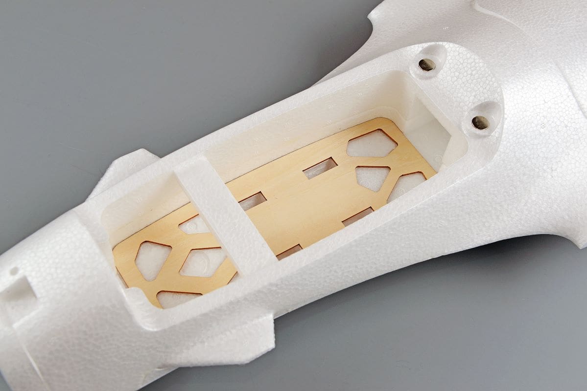
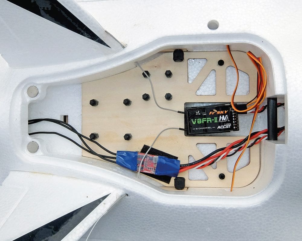
On examination of the fuselage there are two ply plates; one is glued in and holds the LiPo battery whilst the other is for the receiver and FPV equipment. Standoffs are supplied for fitting the various FPV boards and this board requires gluing in once the standoffs have been fitted. It is a very nice touch to have all the standoffs supplied.
The construction page supplied with the kit is very sparse on information. However, there is plenty of information on the web, both on YouTube and the RC Groups forums. Having said that, when I looked to find information about how to solder the wires onto the ESC/BEC I couldn’t find anything. So, after looking carefully at the ESC I made a judgement call and soldered the wires accordingly. My assessment worked and a photo showing how to wire the ESC is shown nearby. I didn’t fit the ESC into the slot provided in the underside of the fuselage as landing the model on wet grass could cause problems. Instead, I fitted it using Velcro to the ply plate.
I glued on the additional motor backplate supplied to give plenty of wood to screw the motor to. Once the glue had cured the motor was screwed to the two 3mm ply plates using the supplied screws.
The wing servos were checked out using a servo tester and after verifying that they were working okay they were hot glued into the wing. The pushrods and ball link fittings are bolted into the horns using the supplied nuts and bolts. It was nice to see a double horn being used at the elevon ends of the pushrods, and also the thin slots preformed in the foam to push the servo wires into.
The V-tail feathers were then hot glued into place. The joints are a nice, accurate fit so there’s no problems with gluing them in at the wrong angle. However, an issue I did have was that I applied hot glue to the bottom of the fins, but this stopped them from seating down fully. If using hot glue only apply this to the sides of the fin slots.
The receiver was Velcroed to the fuselage and the aerials were taped to the V-tail leading edges.
SETTING UP
All that was left to do was to set up the control throws and balance the model on the points moulded into the bottom of the wing. This is a nice touch and ensures that the model balances correctly.
Finding set up information on the control throws was a problem as nothing is given on the construction page. Scouring the internet (after an hour of looking!) I finally found someone who had set his control throws to 10mm up and down on both ailerons and elevators, so mine was also set to these throws. I also added 40% exponential.
I am using a 4-cell 1000mah battery (as that’s what I have) and when using the supplied Velcro strap to hold the LiPo in place it doesn’t quite balance the model. Ideally, it would probably need a 4S 1300mah battery. Therefore, a small piece of lead was needed to balance the model.
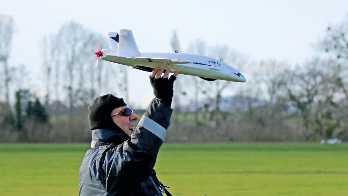
I cleaned the model with soapy water, dried it and then applied the decals. After that all that was left to do was to test fly the Dolphin!
MORE REFLEX PLEASE
The day of the test flight was cold but with light winds of 5mph and plenty of sunshine. After checking all controls and performing a range check there was nothing left to do. The model was launched on full power by my clubmate Steve and as it sunk towards the ground some up elevator was applied. Once at a suitable height more up elevator was needed as the reflex built into the wing proved to be insufficient.
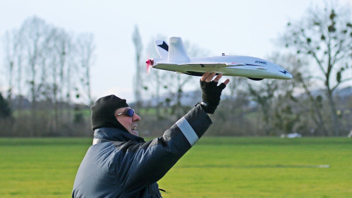
The first flight went okay but the controls were a bit twitchy. So, the model was landed, and expo was increased to 60% on both controls and the reflex was increased by 3mm from the recommended setting.
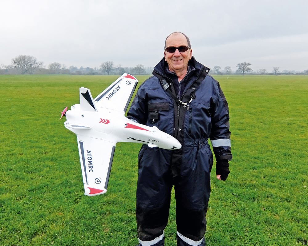
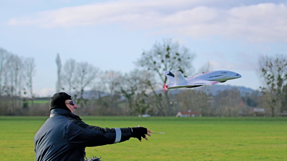
I launched the model myself on the next flight and this time the model flew straight from my hand with no problems. The controls were nicely harmonised, and the model grooved around the sky on full power at a decent speed. But when climbed vertically the Dolphin did eventually run out of steam.
When power was reduced the model slowed down but was still found to be nicely responsive to the controls. Landing the Dolphin consists of throttling back and letting the model slowly sink. Then, just before touching down, shut the throttle and the model will slide to a halt. No problems have been encountered with the propeller hitting the ground on landing.


