In the first of a two-part feature Kenny Morton describes his build of an impressive Search & Rescue helicopter
words >> Kenny Morton
photos >> Kenny Morton, Paul Collins
Enjoy more RCM&E Magazine reading every month.
Click here to subscribe & save.
I don’t know it’s normal for people who build scale models but the trigger for me to start on a new project is frequently the demise of an old one. I wrote off a Jet Ranger and out of that came a Cobra. The same thing happened with my Squirrel, which triggered the arrival of an Airwolf. Funny, then, that it should be a ‘rapid unscheduled disassembly’ that triggered the beginning of my latest project, as one fine Sunday afternoon, shortly after rebuilding my Airwolf for the second time in a year, it did a very passable impersonation of a dropped brick!
The result was rather depressing; so depressing that I decided that the Airwolf was going to have to remain in a coma for the foreseeable future.
Time for a new toy, but ‘Shhh’, don’t tell the missus!
DECISIONS, DECISIONS
Searching for a new model to build is normally a process of elimination for me. Eventually the AW139 kit by Vario ticked all my boxes but as with most things scale the initial outlay was a difficult pill to swallow. However, nothing else was coming close to ‘floating my boat’ so I coughed up the funds to order it.
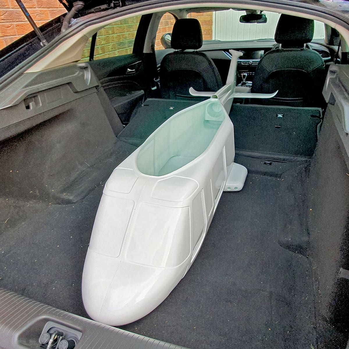
Having specified my work address to get it delivered to there was an excited response from the post room one morning, “Kenny, there is a MASSIVE box here for you!” When I got to the post room, there it was, blocking out the sun. Now that IS a big box! My immediate thought was ‘How am I going to fit this in the car?’ Thankfully, it did – just!
FULL SIZE RESEARCH
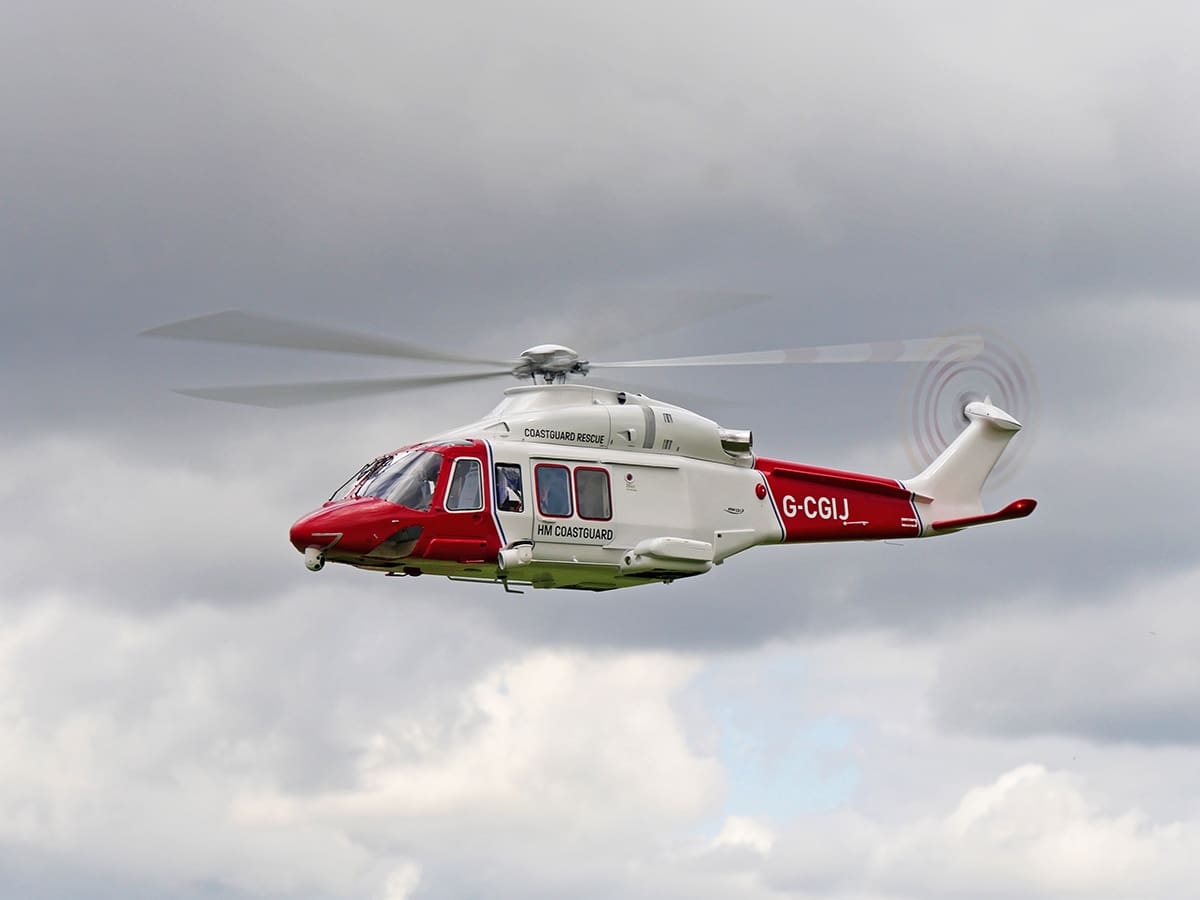
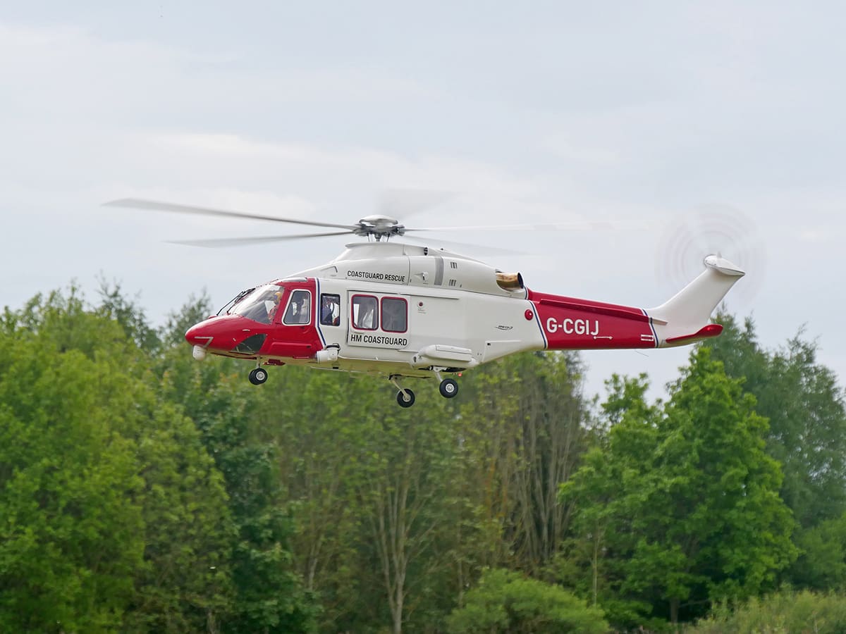
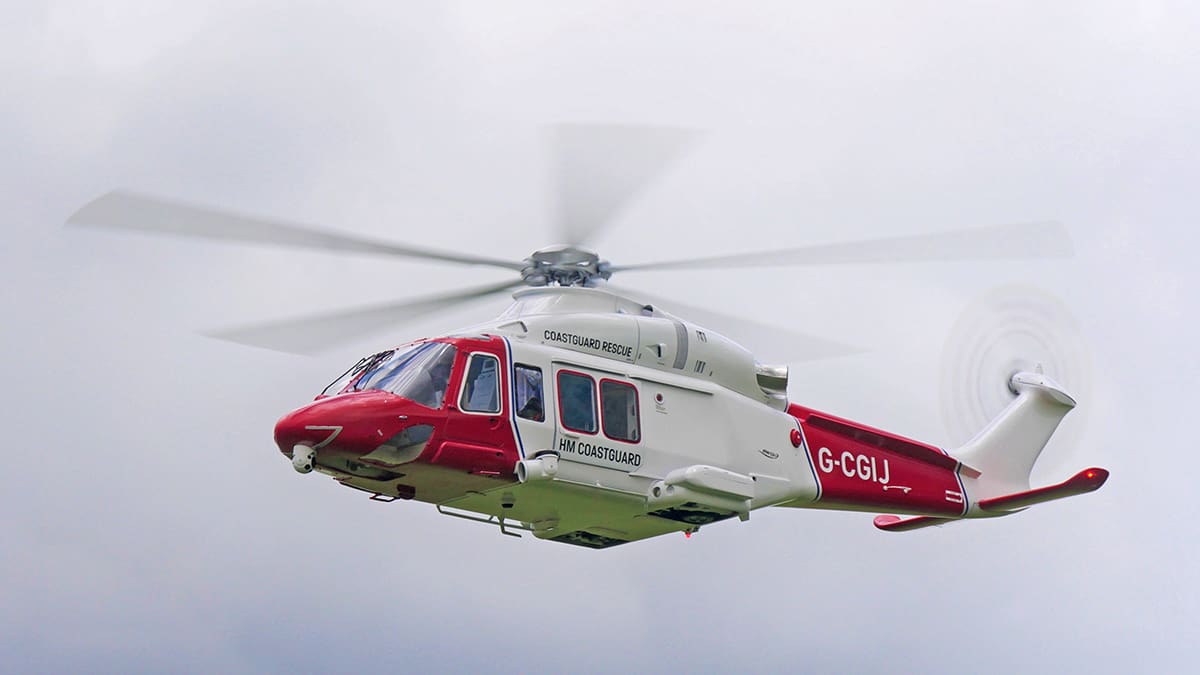
Unusually for me the decision on which full size helicopter to use as a subject had already been decided. I always like to try and get in touch with whatever organisation owns the helicopter I choose to model, even if it’s just to say, ‘I’m doing this.’ To that end, I got in touch with HM Coastguard, as I was going to be modelling one of their machines. Their response was extremely positive, and I must credit them with an awesome public relations policy. They provided me with some excellent reference material to use, but I very quickly found out that HM Coastguard is now using AW189s. Unfortunately, there are several very significant differences between the 139 and 189, so I decided to keep with the HM Coastguard theme and to build a recent, but not current, helicopter.
THE GATHERING
Getting the kit is just the start of the process. Unless you get a ‘super combo’ or an RTF machine, there is always more to buy. This is especially true for a scale bird as just about everything, such as the electronics, needs to be obtained as an ‘extra’.
I try to get this out of the way sooner rather than later, so I bought, with the kit, Vario’s recommended motor and speed controller, a Kontronix Jazz HV120 and Pyro 700 motor.
I also ended up with a 20 channel Spektrum receiver and a Bavarian Demon gyro. Finally, I purchased five Savox 1267 HV servos.
IN THE BEGINNING
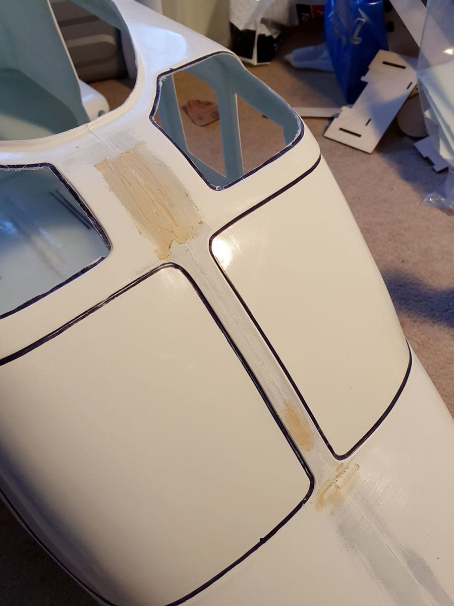
As with most of my scale helicopters I began by taking a Dremel to my extremely large financial investment and cut out the window and door holes. This is a scary thing to do as one cut in the wrong place and you’re fixing things straight away.
What I do is to draw round the thing I’m cutting with a Sharpie. Then I cut well inside the line, and I file out to the line. This minimises the chance of mistakes because a Dremel cutting disc goes through glass fibre like butter.
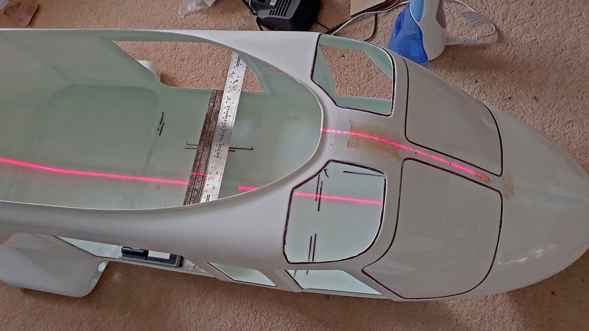
With the windows cut out the next thing to do is to establish the centreline of the fuselage and where the woodwork will go; getting this right is easier said than done because often where a former needs to go doesn’t exactly match up to the contours of the fuselage, so a great deal of test fitting and filing of the formers is required.
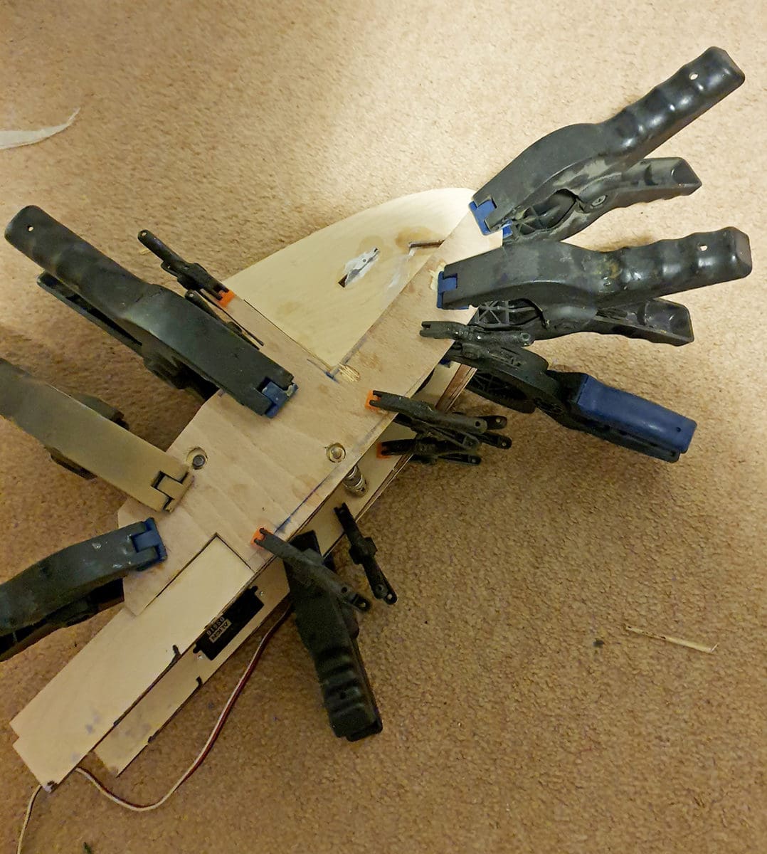
I built up the nose gear and mounted it between the nose formers. Test fitting the pre-cut nose formers revealed that the contour of the nose was very different to that of the former, so I built a ply overlay and epoxied that to the former. Then I was ready to glue in the nose end woodwork using high strength industrial epoxy, which costs a fortune and needs a special applicator. Once the nose woodwork was secure the next thing to build was the main undercarriage.
UNDERCARRIAGE
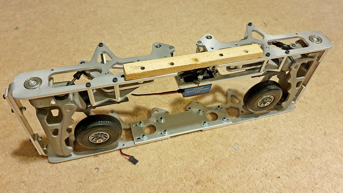
The main undercarriage is a very robust aluminium ‘band’ that has two big aluminium castings to take the main wheel ‘swing arms’. After the main gear was built, I was able to begin to shoehorn it into the fuselage. ‘Shoehorn’ is a bit of an understatement because for a while it looked like Christmas in the workshop, because the place was white with glass fibre dust as the sponsons that contain the gear slowly accommodated their new roommates!
Eventually the position was set, and I could glue down the centre section woodwork. Once dry, I pulled out the main gear and began making it work like the real thing, since my research on the full-size helicopter revealed that the main undercarriage retracts quite differently to how Vario would usually have it working. Basically, the swing arm that the main wheel is attached to hangs down quite a bit on take-off and when the full-size retracts its gear the first thing it does is to compress that swing arm and then it folds the gear away. Vario’s gear is designed to fold away with the swing arm ‘swinging’, but my eye for detail wouldn’t accept that and I had to try replicate the full size. Why? Well, stuff like that is cool. The unfortunate thing about that is it increases the complexity significantly.
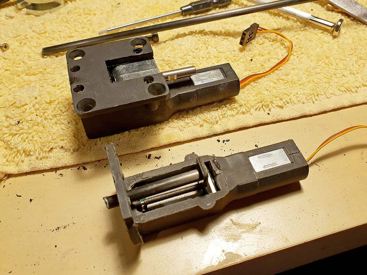
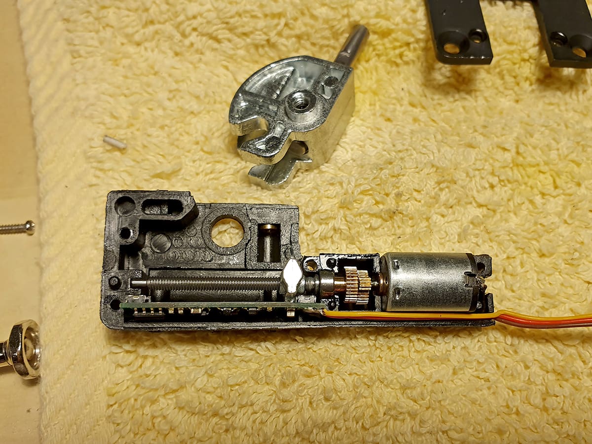
Playing around with ideas for a while, I found a video of how somebody else had done it with their model so rather than re-invent wheels, I proceeded to shamelessly copy it. I had a word with Nigel, who had been involved in the build of this other machine and found out how they did it. I bought some cheap model plane retracts, then I immediately opened them up and ‘redesigned’ them to create a ‘push arm’. I then glued the push arm into the casting of the main gear, so it could now push the swing arm, so it lifted before folding – job done!
By this point, however, it was obvious that the original design is extremely difficult to get set up correctly, so I reworked it to include another servo. To orchestrate this increasingly complex system I bought a programmable sequencer. If you ever build a scale model, please note that scale models, especially helis, are money eating monsters!
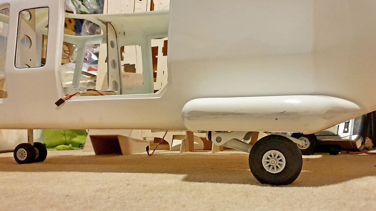
Finally, I had a working undercarriage, and the beast could now stand on its own three wheels. Time for a break to reflect on my milestone being reached.
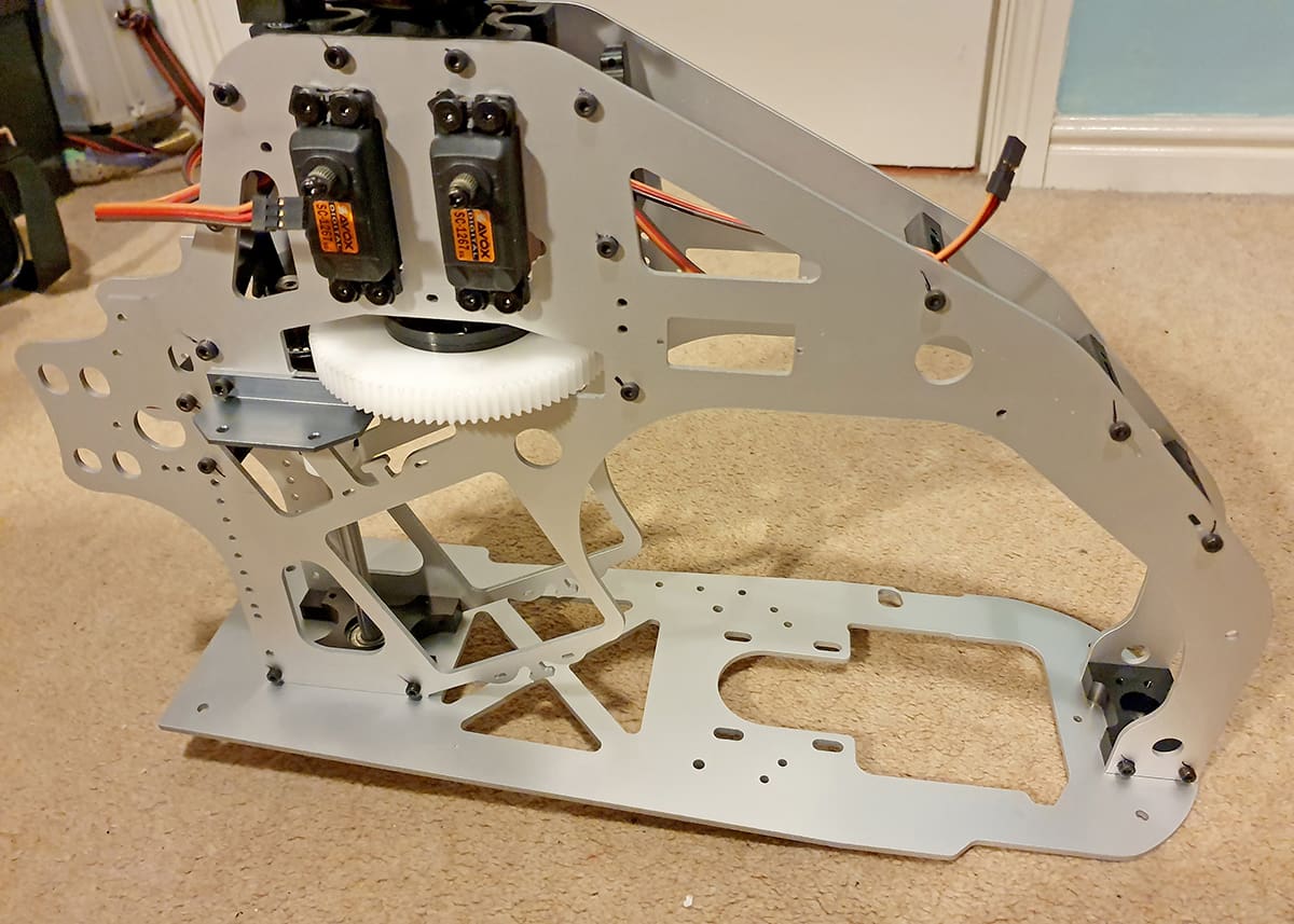
MECHANICS
I then began to work on getting the flying bits of this machine in order. As with all scale helicopters there is a large element of ‘Catch 22’ as you can’t fit the tail boom until you know where to put the tail rotor, and you can’t fit the tail rotor until you know where to put the holes. Unfortunately, you can’t position the holes accurately until you fit the tail boom!
In the instruction manual the installation of the tail rotor and its required hole is cheerfully illustrated with a ture of a Dremel, and the word ‘Cut’ – but I know I need to cut, but where?! If this hole is even 3mm out of position, bad things will happen.
Going round in circles like this will be a well-known feeling for most scale modellers, and I am no stranger to it either, so in the spirit of eating the elephant ‘one bite at a time’, I worked on something else – the mechanics.
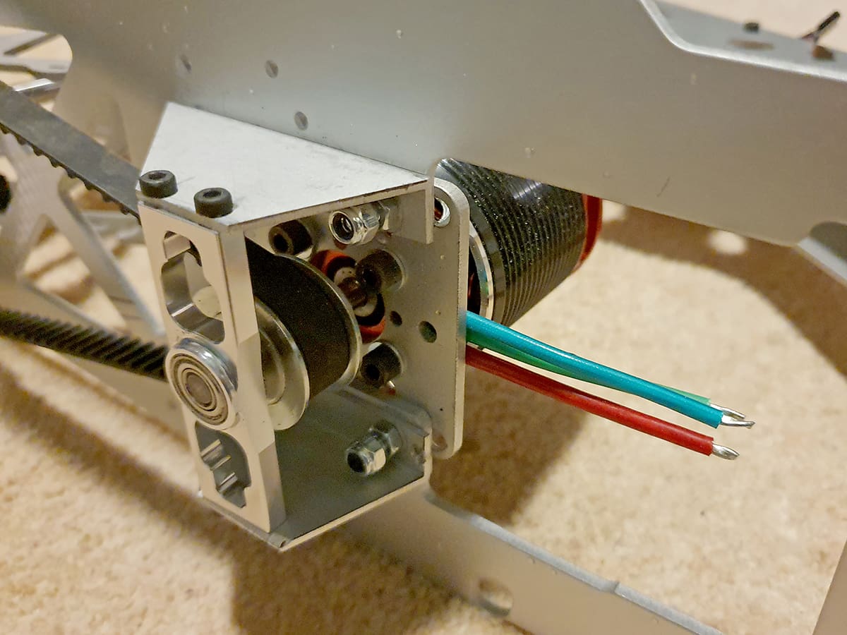
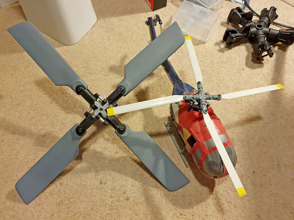
Overall, the build of the mechanics went smoothly. That was up to the point where I installed the motor and its drive belt. When I squeezed the belt, I noticed that the motor shaft was being stressed. Since I have bad experiences with motor shaft stress, I therefore created a second bearing using T-Rex 700 parts and aluminium L profile. Once done, I test fitted the mechanics so that I could begin to figure out where to make the main shaft and tail rotor shaft holes. Once they were done, I could get back to the initial job of sorting out where the actual tail rotor should be. But the first order of business was to actually build the tail rotor; this, ironically, is the same size as my E-flite BO-105 main rotor!
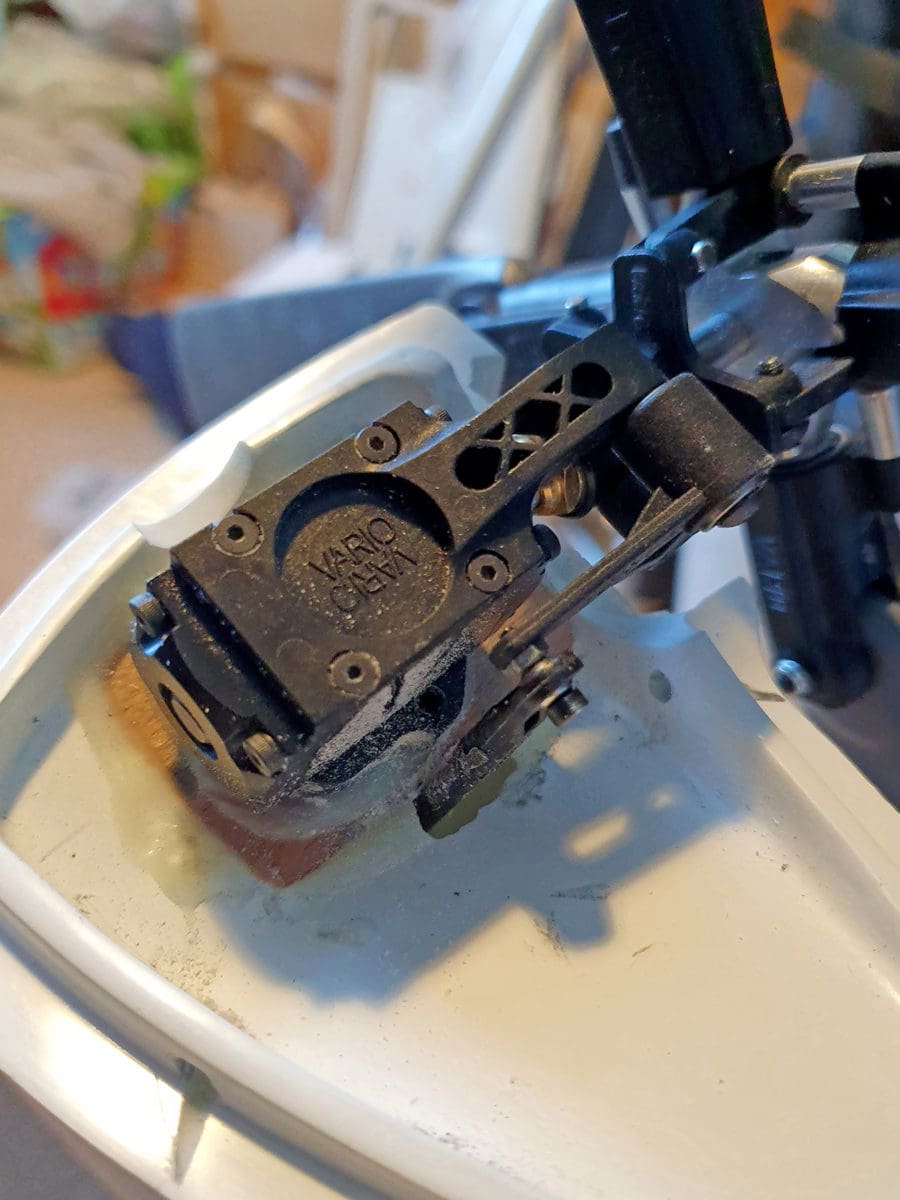
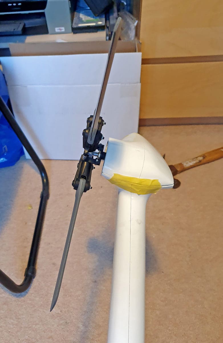
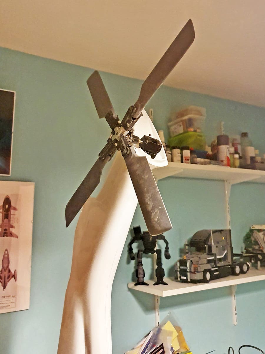
The AW139 is like many modern helicopters in that the tail rotor is off axis from the vertical. I’m not sure of the reason for this, but I suspect it is something to do with helping to lift the tail in cruse flight. When I temporarily fitted the tail rotor to the provided surface, something didn’t look right. It just didn’t seem as raised as the full-size helicopter. After doing some research I found the full-size is angled up by 11 degrees, but my model was only at three degrees. Since this is a feature of the full-size helicopter that I particularly liked, I improved things by sanding a wedge-shaped piece of ply and fitting it between the tail boom and the tail gearbox. Finally, after much faffing about it looked right.
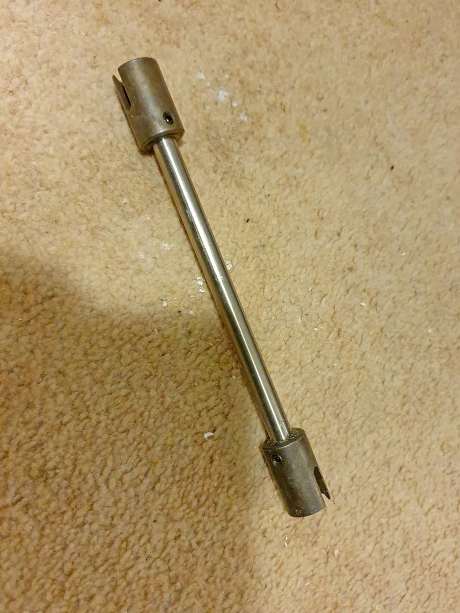
The next thing to do was connect the tail drive. There are two ways to achieve this: either fit a ‘flex’ drive or use an intermediate tail gearbox. Both have their merits, but I have had previous bad experience with using lumps of wire when driving tails. Admittedly, a proper flex drive is probably miles better, but I chose the intermediate tail gearbox. This is fitted tightly to the tail boom tube, followed by a short driveshaft that connects to the tail rotor gearbox. I first had to figure out the size of this driveshaft, then I had to build it up.
Finally, I could install all the ‘stuff’ to make the connection. This is easier said than done and much colourful language ensued before I finally got it all connected. It’s a huge milestone and very satisfying when you can spin the rotor head and the tail spins too.
ELECTRONICS
I began the electronics installation with the receiver. The 20ch Spektrum Rx can handle two batteries for redundancy, and I began by attaching EC3 connectors to the pair of Optipower batteries I had purchased.
That done, I started connecting the electronics. Only there was nowhere to put the Bavarian Demon gyro. I therefore bent a piece of sheet aluminium to put between the frame sides and mounted it on that.
Once everything was completed – all nine channels of it – I tested it but something was wrong. Vario unusually uses four servos to control the swashplate but only three were moving. Then it dawned on me. I went into the settings of the Demon and found that ‘Swash type 3 servos’ was selected. I clicked the 4 servos option and, boom, the ‘broken’ servo sprung into life.
Now that the gyro was operational, I moved onto the speed controller and the motor. I ordered a 160-amp Emcotec battery switch and once that was installed, I could do a run up for the first time.
FIRST RUN UP
The ‘First Run Up’ is the first time you get an indication of whether you have built the machine properly or not. I turned on the transmitter, connected all the batteries and everything beeped like it should, so I raised the throttle and she started up – only backwards! I changed over two of the three motor wires but now the tail was wrong.
It took me a while to figure out that a gear in the tail gearbox was at the wrong end of the shaft. That fixed, I ran it up one more time and everything seemed to work nicely. This opened the door to the next milestone, but first I had to take it all apart again…
THREE STEPS FORWARD…
If you ever read the build instructions of scale model kit, they will show a steady progress from the start through to the end. That may be true for an Airfix model, or even a Billy Bookcase, but it isn’t often true for a scale model heli kit. A more accurate description is three steps forward, two steps back!
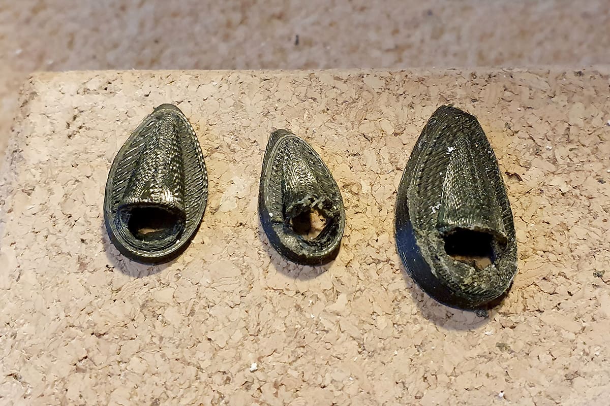
So, I took the boom off and the mechanics out to prepare to marry the boom to the fuselage. But before I could begin to do this, I first had to install the tail lights. And before I could install the lights, I had to make holders for the lights. To make these, I first had to get a good look at what they really looked like, so it was back to my research tures. Next I designed something on CAD and printed it on my 3D printer, then I had to make it fit the model. The beacon was the easiest but the nav light holders took several attempts.
With the light holders fitted, I ran wire from the fuselage to the tail. I used a computer ethernet cable, which conveniently has enough wires. I laid it into the tail and connected the LEDs.
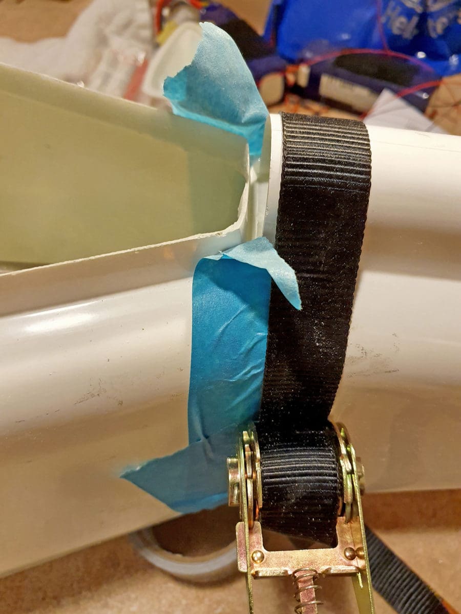
Now it was time to permanently join the tail to fuselage. I began by removing the gelcoat from the mating faces, then I drilled a bunch of holes in the faces. Next, I prepared a nylon ratchet strap and liberally coated the mating faces with epoxy. The tail was then pushed onto the fuselage, aligned and the strap was tightened until epoxy oozed out of the joint. I left it overnight and by the next evening the marriage ceremony was complete, and I could clean up the mess.
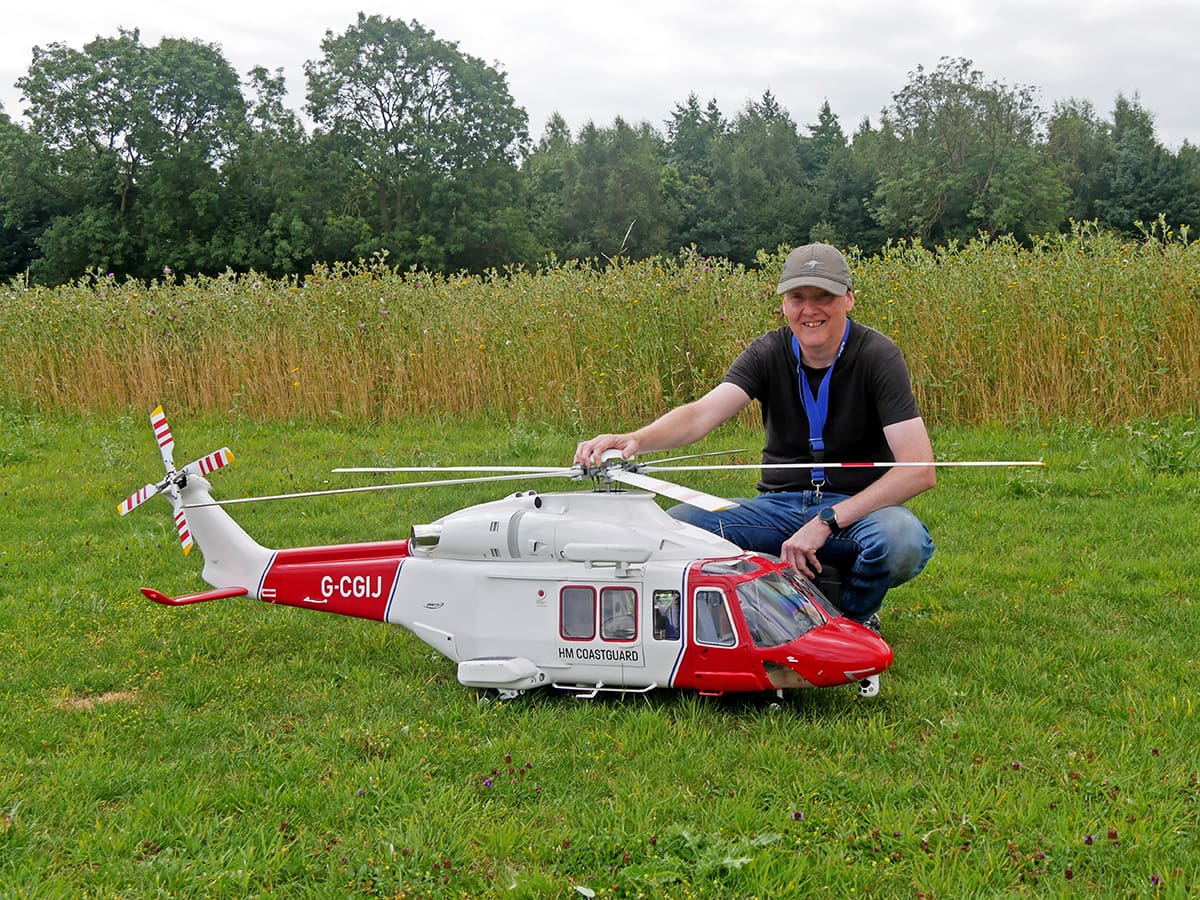
Once the tail boom is on the size of the model really hits home. The body took up the entire floor and whenever I moved it, it would bang the tail on the ceiling light. It was getting awkward, but the next milestone had been reached.