Jeff Barringer resolves to build a replica of the Bugatti air racer from the late 1930s
Most of us know the name Bugatti, not usually in the context of aircraft but rather for the ultra-fast Veyron and Chiron models, as well as many vehicles pre-WWII.
Ettore Bugatti was an Italian-born Frenchman who established his motor manufacturing plant in Molsheim, Alsace (then in Germany) in 1909. In the following years the factory produced a range of vehicles as diverse as the ultra-efficient Grand Prix cars, through open tourers and saloons, to the exquisite Royale. Ever a perfectionist, Bugatti ensured that the design and implementation of his vehicles reflected this philosophy.
Enjoy more RCM&E Magazine reading every month.
Click here to subscribe & save.
Aware of the importance of sport in the promotion of a brand, in 1938 Bugatti, in conjunction with Louis de Monge, started work to design an unlimited air racer to compete in the Deutsch de la Meurthe Cup Race. The design incorporated two Bugatti Type 50P supercharged straight eight engines mounted amidships. Of 4.9 litres capacity and developing 450HP each engine drove forward to propellers which were co-axial and contra-rotating (probably to counter the massive torque effects of so much power). Making wide use of magnesium and balsa the aircraft was the source of five modern patents, including the inline/coax engines, V-tail mixer controls and an automatic flap system.
With a design maximum speed of over 500 mph, at a time when a Spitfire could manage 360 mph, Bugatti was approached by the government of France to use the technology of the racing aircraft to develop a fighter variant for mass production. However, with the outbreak of World War 2, the imminent fall of Paris and the strategic importance of the prototype had it fallen into Nazi hands, Bugatti had the aircraft disassembled and hidden on his country estate.
The aircraft remained hidden throughout World War II and Bugatti died in 1947, having never resumed work on it. The hull was sold several times and its twin Bugatti 50P engines were removed for automotive use. In 1971 a restoration effort was started using original blueprints and eventually the aircraft was transferred to the EAA Aviation Museum collection in the USA where restoration was completed and the 100P remains there on static display.
So, the prototype never flew, but at the turn of the 21st century three Americans built an accurate reproduction powered by a pair of Hyabusa motorcycle engines. This aircraft managed three flights before a transmission failure on take-off caused the machine to drop into a stall-spin, the resulting crash killing the pilot.
SCALE APPEAL
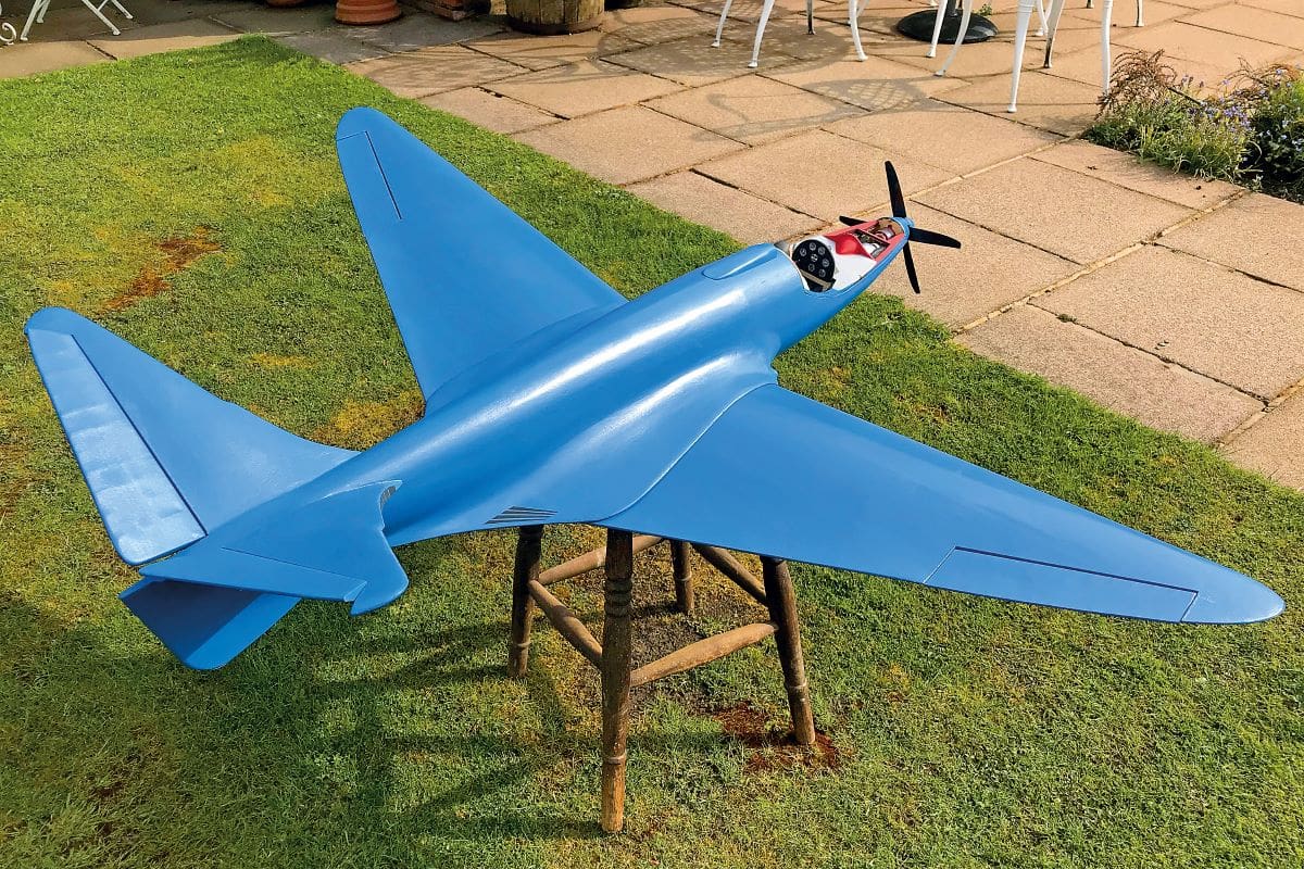
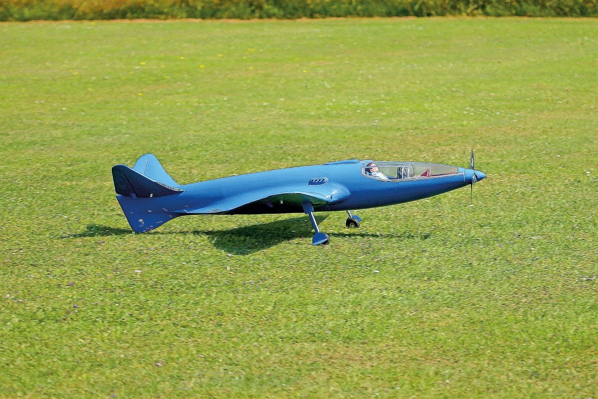
In spite of this uncertain history, the Bugatti 100P has always appealed to me, combining stunning looks with technological innovation. Having searched for a plan, quite by chance I came across a reference in an old magazine for a 1.5 metre model from a French designer. Reportedly there was a plan and an associated part-kit and so I attempted to contact the designer and the vendor of the kit, who turned out to be two separate entities. I’ll say no more about the legendary ‘service culture’ in France but suffice it to say that after what I consider an awful lot of effort and chasing, I received the part kit, plan and instructions (in French) by post for what many impecunious modellers would consider quite a lot of money. In fairness the laser-cutting and accuracy of the kit were good, and the plan was okay, although missing important details and being printed rather faintly, presumably to avoid copying.
I already had a contra-coax motor (you may recall my predilection for these from my Sea Fury article in the February 2021 issue of RCM&E) and I had a set of retracts of the exact correct size, so all I needed to add was some balsa sheet, servos and receiver to complete the model. Careful study of the plan was followed by translation of the documentation from French with the help of the daughter of one of my aeromodelling buddies and some simple calculations to get a feel for the model. Quoted weight was 2.33 kg (81oz) with battery, ready to fly, and the wing area worked out to pretty much exactly four square feet, so at 20 oz/sq ft the wing loading was reasonable for a model with a span of almost five feet. The wing root was thick at 2.25 inches, indicating good lift at low speeds, and the C of G marked on the plan calculated out to give a static margin around 17.5%, again reasonably benign. So, although the appearance of the aircraft appeared radical the maths said that it was going to be okay. Fingers crossed!
Back to the plan and the use of the contra-coax motor meant that the front-end had to be re-thought since it is longer and narrower than the traditional outrunner. But the good news was that the shape of the prototype is such that the Centre of Gravity was approximately half-way between the front and rear extremes of the model. Given the long battery box forming the central core of the model it meant that balancing by positioning the LiPo would be relatively easy.
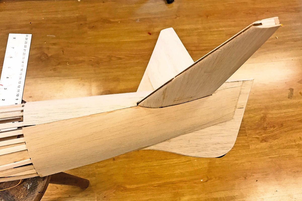
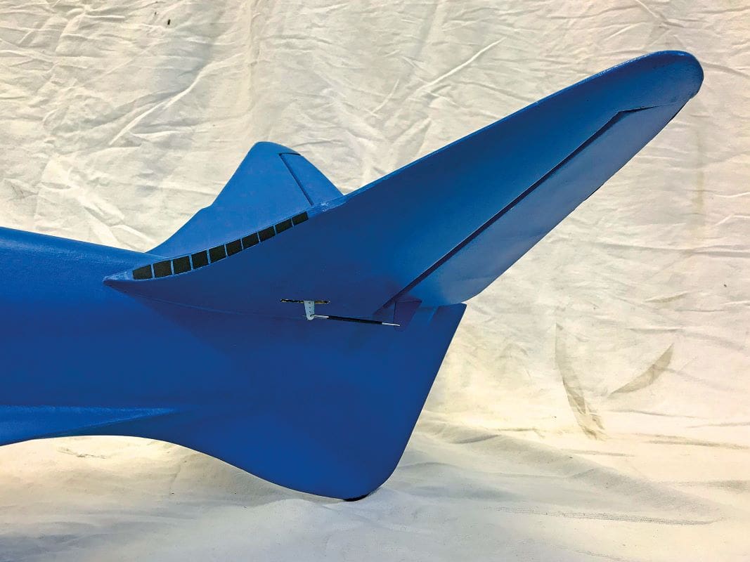
At the rear the ruddervator control servos (rudder and elevator) were shown on the plan as standard size units mounted in the rear of the fuselage. Instead, I decided to use a pair of servos mounted inside the rear stabilisers. This would remove the need for a pair of rather ugly pushrods running along the sides of the fuselage and also the need for a rear access hatch, which was really good news as I dislike hatches.
Talking of which, a further hatch was shown atop the model on the plan for access to the battery. But study showed that if I made a readily removable canopy, I could hide the battery hatch behind the pilot. Bingo – no external hatches!
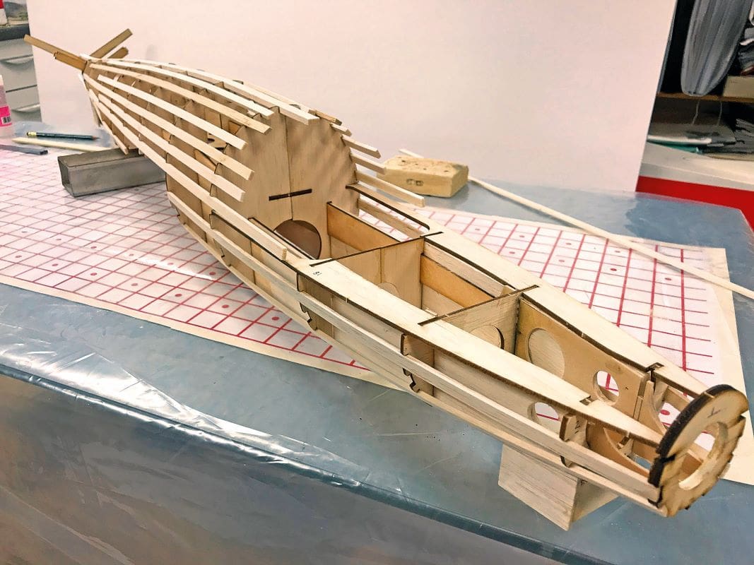
FUSELAGE
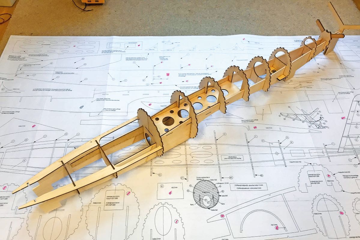
The fuselage consists of a box construction with formers laid out to carry the longitudinal stringers, which in turn support the balsa skin. The fuselage box sides are longer than standard 36-inch balsa sheet and so a splice is called for on the 3mm sides. I used a scarf joint in the cabin area where it would be braced by the ply wing/fuselage doubler.
Some of the formers had to be cut and re-joined in order to fit them and I modified the nose and added ply bracing to carry the contra-motor.
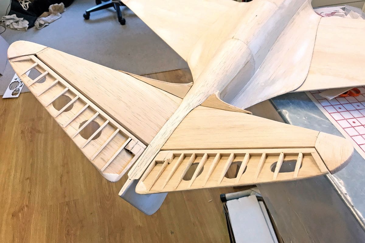
During the fuselage build two ‘Y’ shaped braces are added to carry the rear ‘V’ and the stabilisers are skinned before the main fuselage, enclosing the servos. I opted to construct the rear control surfaces at the same time to discover that, if built to plan, due to the ‘V’ the surfaces collided when up-elevator was applied. Not a major problem at that stage but it would have been very annoying had it been discovered after covering.
It could be argued that the number of stringers was overdone, but the technique does make it easier to fit the 1.5mm balsa skin as there’s always a stringer available for gluing. The upper fuselage was sheeted first and then it was necessary to build the wing so that the wing/fuselage fillet could be sorted.
WING CONSTRUCTION
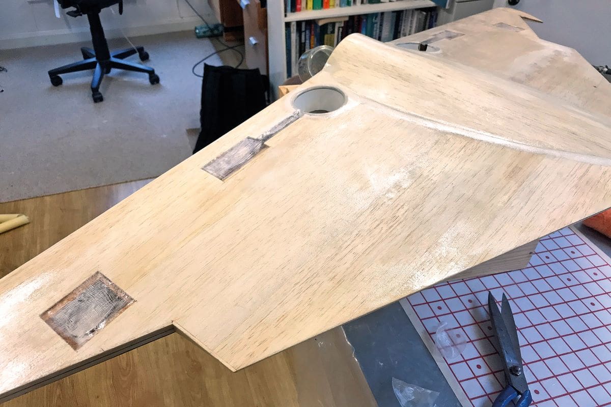
The plan called for a fairly traditional wing build with ribs and spars, and spar webbing for added strength. A box ‘D’ section is created at the front and sheeting at the rear is cut out to create the ailerons. I had already decided that my Bugatti would have fully sheeted wings, as I intended to glass-finish it, so I made up sheets of 1.5mm balsa and covered both the top and bottom.
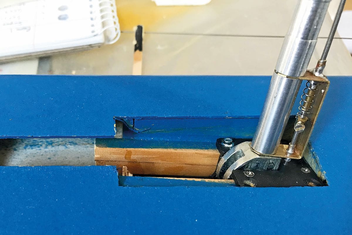
Before taking this step, I spent a considerable amount to time trying to sort out the retract mechanism. The plan showed the wheels retracting into and cutting the main spar, which goes against my instincts.
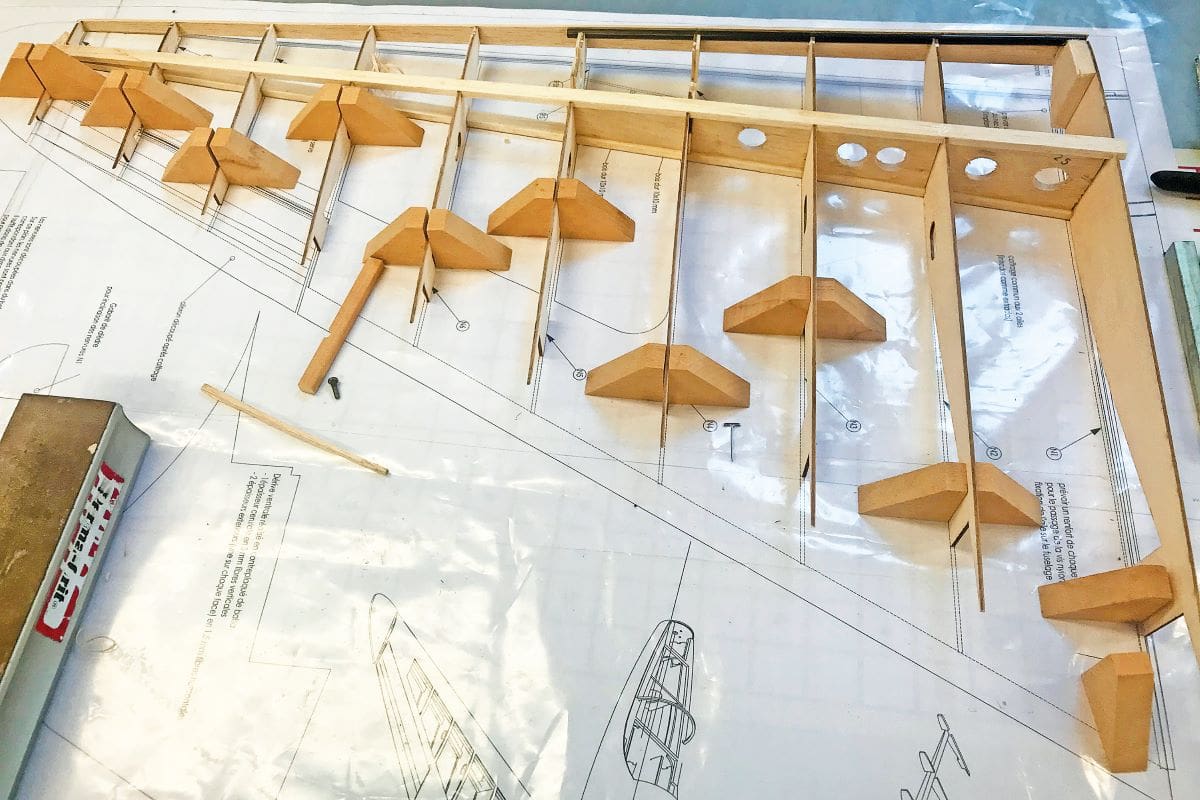
Looking closely at the plan there is a substantial wing/fuselage fillet and also a support pod beneath the wing. But I still felt that a heavy landing could do a lot of damage and so I added full-depth balsa blocks between the spars, out as far as the undercarriage mount, and I built a length of carbon fibre rod into the leading edge on each wing half. In addition, after a good deal of consideration, I adjusted the throw of the undercarriage mechanism and opted to use smaller wheels in order to avoid cutting into the main spar.
Once the wing was sheeted the ailerons were cut out, faced and then the wingtips added. These were made up using thin glass fibre sheet laminated on each side with block balsa in order to make the vulnerable wingtips ‘ding’ proof.
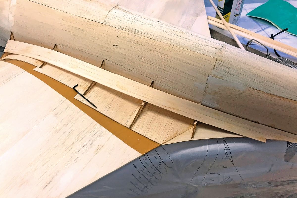
WING TO FUSELAGE FILLET
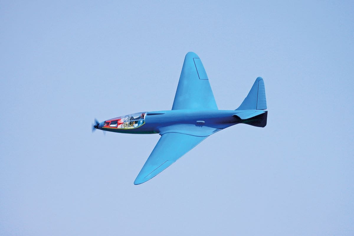
There is no doubt that the radical appearance of the Bugatti owes a lot to the wing/fuselage fillet, known as the ‘Karman’ in French.
The wing was placed onto the fuselage, separated by a thin polythene sheet to avoid gluing the two together, and then small formers are added to define the shape of the fillet. My usual practice at this point is to attempt to shape a thin cardboard fillet and use this to define the same shape cut from thin ply, which then becomes the fillet. But in the case of the Bugatti the compound curves involved made that process impossible and so I obtained the correct shape by planking with 7 x 2mm balsa strips. The process was slow and painstaking, but a really nice shape resulted, giving a perfect wing saddle.
D DOORS
Once the planking was complete the leading edge fuselage blocks were carved from balsa. The prototype has distinctive air intakes at this point, which were duly reproduced using handy lengths of black plastic tubing.
As mentioned above the underside of the wing at the centre section is well braced by skinning with 2mm balsa sheet. The wheel wells are keyed into this and lined with cut-down yoghurt pots.
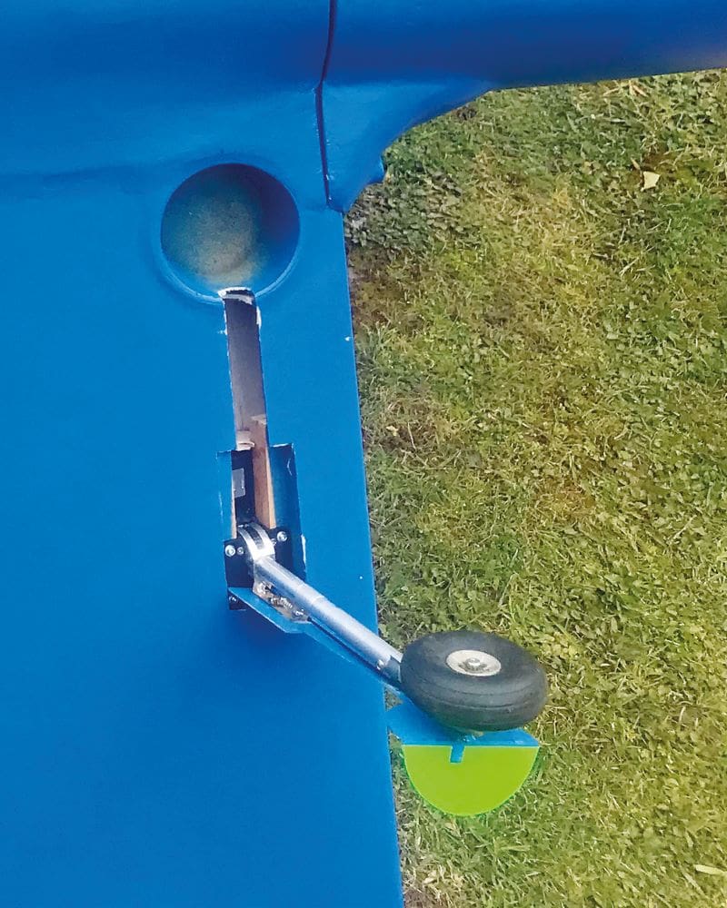
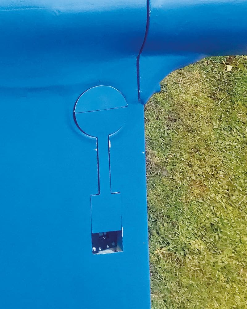
Working D doors to fair off the wheels are a distinctive feature of the Bugatti.
On the prototype, the undercarriage fairing folds at the wheel to provide clearance when on the ground, known as ‘D’ doors, a nice feature which I emulated using a pushrod bearing on the undercarriage retract mechanism when down. When the undercarriage retracts, the spring-loaded pushrod allows the cover to return to its closed position.
FINISHING
The model was glassed using 18 gm lightweight cloth and G4 resin sealer. This is the first time I’ve used G4 and I have to say that I wasn’t as pleased with the finish as I’ve been with laminating epoxy. So I’ll revert to that for the future, I think.
When finished, the model and all component parts weighed in at just 2kg, including battery.
COCKPIT
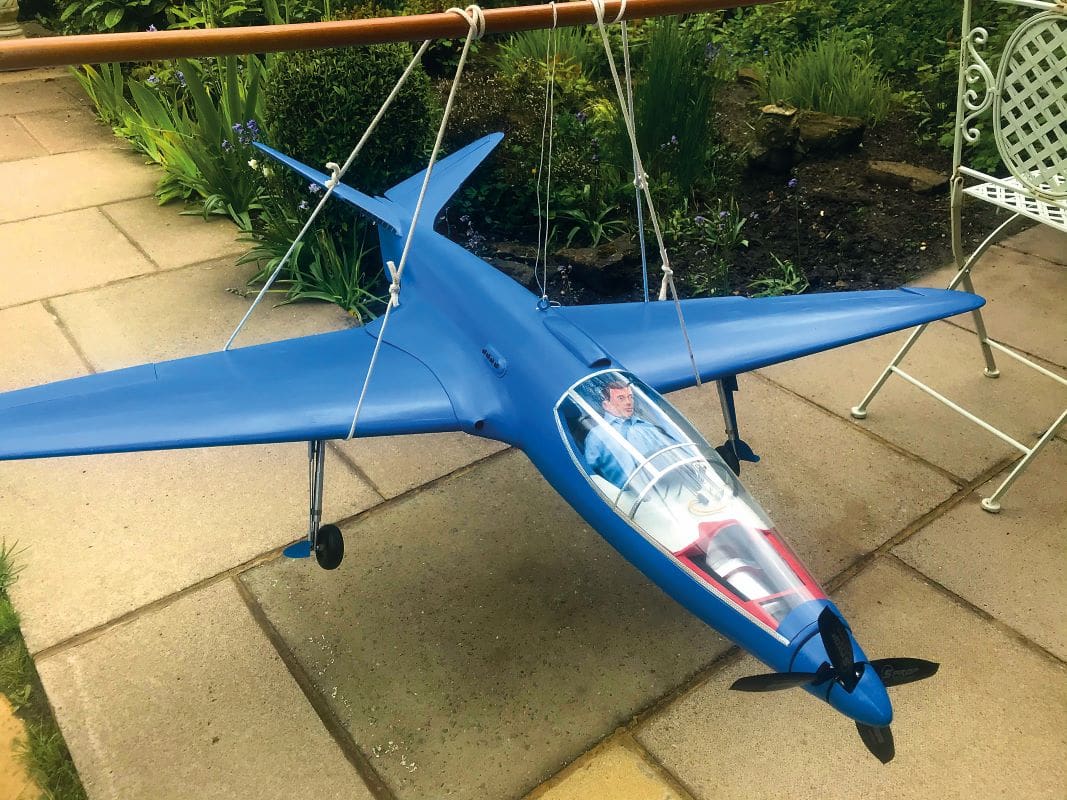
The cockpit glazing on the prototype consists of two parts; a front section reaching forwards to the rearmost propeller hub and a rear sliding section which allowed access for the pilot. Both of these on the prototype were made from clear material reinforced with riveted aluminium strip, making visible the internal make-up of the machine, including the complex gearbox and drive mechanism, as well as the rather vestigial instrument panel and controls. I opted to attempt to recreate this as it is part of the charm of the aircraft, and I was lucky to find a couple of old model helicopter screens that could be adapted to fit in the same way as the original.
The instrument panel is from balsa sheet and the instruments and controls are made from those miscellaneous oddments that every modeller has ‘somewhere, if only I can find it’!

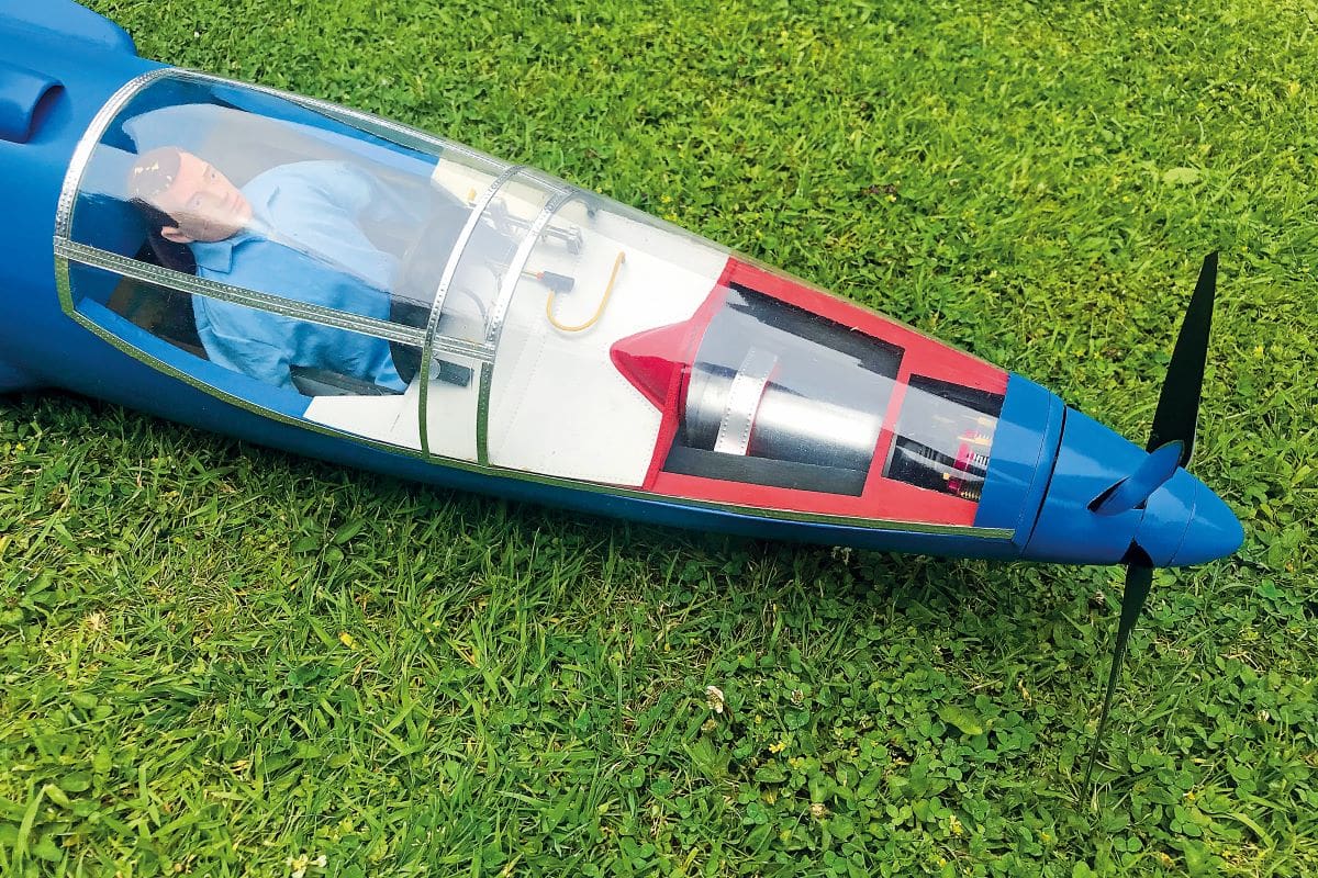
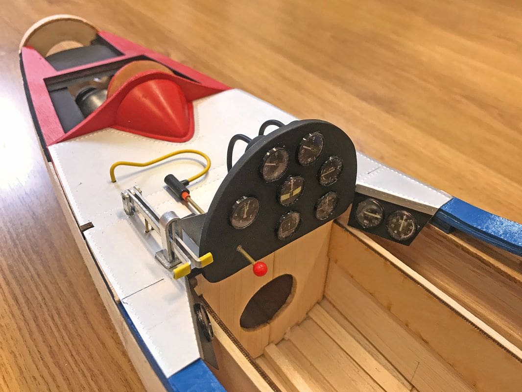
The whole cockpit assembly was made removable and retained by magnets so that the battery, housed behind the pilot, could be easily accessed. With such an open cockpit the pilot is an important consideration and it turned out that an Action Man was a perfect scale fit, and the parachutist version is supplied with a set of rather fetching light blue overalls. Unfortunately, he weighs almost half a pound and so I elected to make a lightweight version by taking a latex mould of his head and creating a balsa and blue foam body. This allowed a weight reduction from 220g to 25g.
CONTRA MOTOR
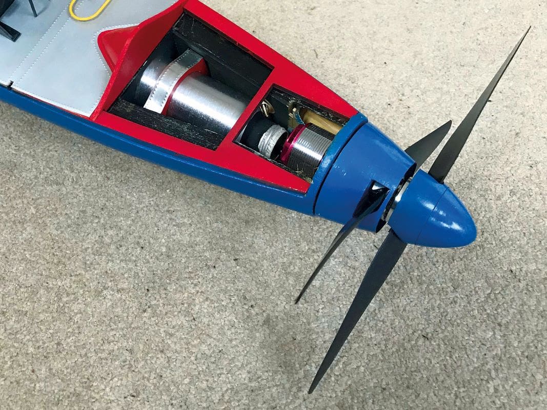
The contra-motor is mounted against the forward bulkhead, with the rearmost brushless motor inside the cabin and the outermost outside. This allowed me to form the counterclockwise spinner from a plastic bottle and then add a conventional spinner for the forward propeller.
The two ESCs are housed on the cabin floor and a weight and balance test using a Vanessa Rig put the balance point exactly on the calculated C of G. This meant that provided the propulsion battery straddled the C of G any weight of battery could be used (within reason).
FLYING
Any model’s first flight is of concern, but the Bugatti offered a few potential challenges beyond the norm:
- The full-size prototype never flew.
- The nose is very long, inviting the propellers to touch the ground on take-off and landing.
- The model appears short-coupled, meaning that the elevator could be very sensitive.
- As mentioned above, the Bugatti was the first aircraft to use a ‘V’ tail. Did they get it right?
- Most experienced aeromodellers looking at the model looked at the tiny wingtips and muttered ,‘Hmm, tip-stall’.
- The unusual shape could cause orientation issues, not to mention aerodynamic issues.
- Information on the contra-motor was very scant, so it was difficult to tell if there was enough power for the model.
On the positive side, if she flew, she’d look great!
FIRST FLIGHT
Prior to the first flight I carried out a brief ground run, only to find that she almost shook herself to pieces when full power was applied using the supplied propellers. The culprit (or so I initially thought) was the rearmost counterclockwise propeller, from which I had to cut almost half an inch before she balanced statically. This was no great surprise as something similar had happened with the contra-motor fitted to my Sea Fury, so I obtained a pair of Graupner propellers and upon spinning them up I found that the vibration level was much more acceptable.
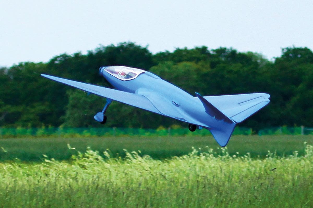
However, the proof of the pudding is in a successful flight and I lined up for the first flight with some trepidation. I was immediately reassured when she ran straight and true under precise elevator control, with no tendency to ‘peck’ the hard runway. She rotated and climbed away but I was surprised and disappointed that the aircraft developed a very severe vibration, only reaching about 50 feet before the canopy was ejected and both propellers detached.
Although the 100P was damaged in the resulting arrival I was able to ascertain that she could glide reasonably well, and I had sufficient control to land on the grass rather than the runway.
Repairs to the aircraft were definitely viable but I had to discover why she had self-destructed and so I dismantled the motor and noticed that there was some play in the bearings. The front propeller is driven from the rearmost motor via a shaft, which itself is supported by ball race bearings. But the frontmost bearing was missing; instead, there was an empty bearing housing – the bearing had never been fitted! So much for Quality Control…
The maiden flight proper took place a couple of weeks later, again with Tony King in attendance for photos. This time instead of a hard runway we used a grass runway, which unfortunately increased the likelihood of the aircraft nosing over and destroying the propellers. I decided to use a high elevator rate and full back elevator to keep the tail on the ground during the take-off run, which actually worked, and she shot into the air after quite a short distance. Forward stick, gear up and reduced elevator throw soon had the Bugatti sorted and she climbed away strongly. After a couple of clicks of aileron trim, she was taken to a safe height and into a throttle-off stall, where she simply mushed and I still had aileron control, so no worries there.
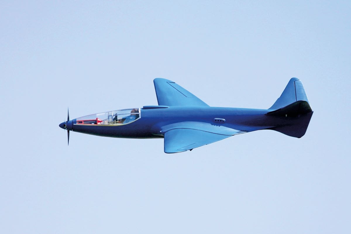
After this albeit very brief introduction I found the Bugatti responsive to all controls, possibly a little over-responsive to elevator due to the short coupling, but generally easy and predictable to fly. Power to weight was calculated to be 100W per pound, so performance promised to be ‘sporting’.
Now to sort out the pictures. Back in the day, when I built and reviewed for Boddo, he always told me that he was to be present with his camera for the first flight and I mustn’t fly the model again until he had confirmed that the pictures were good. Great discipline, but it does rather put extra pressure into a maiden flight.
In fact, while looking unfamiliar in the air, she handled very well, and I was able to execute a whole series of passes and banked turns for Tony’s camera. At no time did the handling of the model cause concern, and when my count-down timer sounded at five minutes she slotted nicely into the circuit and descended very predictably and smoothly onto the patch.
Checking the state of the battery on landing the 3S 5000mAh pack was still showing 75% available, which is remarkable. Admittedly, I hadn’t thrashed her, but I had made quite a few descents and climb-outs during the flight.
THE SOUND
As a classic car enthusiast, over the years I’ve witnessed racing Bugattis from the 1930s with their screaming straight eight engines, whining superchargers and staccato tearing calico exhausts. Put that into the context of as many as 20 cars racing around the narrow streets of French towns and you have a truly blood-stirring spectacle.
While we will never know, one can imagine that the sound from the Bugatti 100P with its twin supercharged straight-eights would have been equally spectacular, let alone it’s unique appearance.
Now the great thing about a contra-coax motor is that the sound interference between the propeller blades creates a similarly complex engine note, varying from a virtual scream at full throttle to a very pleasing ‘beat’ at low throttle on approach. Every throttle change can be heard, be it from operator input or from loading. And so for the sound alone the Bugatti 100P is heroic and extremely entertaining to fly.
CONCLUSION
I love this Bugatti. She’s visually stunning, has an impressive pedigree, and sounds, flies and lands really well, whilst doing it all with panache. I am looking forward to getting to know her better.