Shaun Garrity describes the build of a favourite delta slope soarer from the 1970s
words & photos >> Shaun Garrity
My passion for flying wings and deltas is long standing. This was recently re-affirmed when I came across an old Delta Lady kit on one of the ‘Bring & Buy’ stalls at an Old Warden Modelair flying event last year.
Enjoy more RCM&E Magazine reading every month.
Click here to subscribe & save.
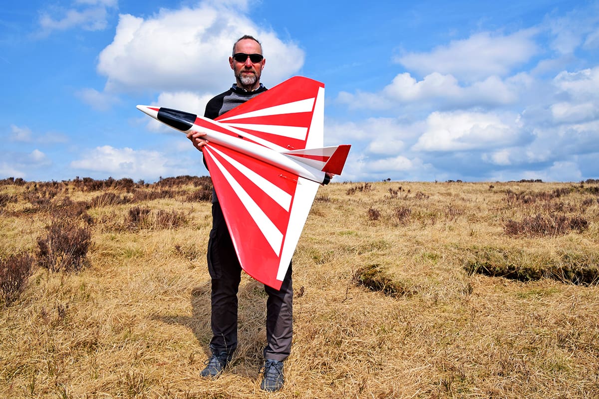
Back in 1979, as a 23-year-old, I remember seeing Delta Lady for the first time on our local slope. This 54” wingspan, plan built, Vulcan-esque delta slope soarer immediately struck a chord as it cut an impressive silhouette hurtling across the skies above our local hill. Performance wise it was keeping up with the aerobats of the day but seemingly floated like a thermal soarer when slowed down.
Just to explain, Mike Trew, a UK modeller, was the designer of Delta Lady and his plan was first published in an American magazine, Model Aeroplane News, I believe. Mike was well known on the UK soaring scene, being the National Scale Sailplane Champion.
Traditionally constructed from balsa and ply it was a robust, but relatively lightweight model, intended to fly in an exceptionally wide speed range from 10 to 50mph, and this was without ballast. Delta Lady proved so popular that Mike updated it with a GRP fuselage, foam wings, and pre-cut balsa and ply parts to speed construction. Branded under the guise of Trew Flite Kits, it was distributed by RipMax and proved an instant hit.
Back to Old Warden and after a swift negotiation with the vendor the kit was mine, as I had decided I wanted to build another one to reacquaint myself with this excellent model. My original plan-built Delta Lady, after many flights, had an intervention with a huge boulder, turning instantly to balsa confetti (and, yes, it was pilot error – my dumb thumbs had struck again, so no excuses about hardware failure or interference). I wanted a quick fix replacement as the model had become a firm favourite, but the traditionally constructed one, although not a complex build, would have taken more time than I was prepared to give up. So, I dug deep, handed over the £44.50 asking price and purchased the new Trew Flite quick build version.
From memory it went together with no fuss, and everything fitted as intended. One idea floatedaround at the time was to cut out chunks of foam from the wing to save some weight and when the kit was reviewed in March 1981 Radio Modeller by Keith Thomas this mod saved approx. 4 oz., but it was a degree of effort I couldn’t be bothered with. Besides, our local slope was festooned in heather and other very spiky plants so wasn’t very ‘open wing structure’ friendly, with punctures in film coverings being a frequent occurrence.
Anyway, back to my newly planned retro Trew Flite quick build kit…
For a change I thought I wouldn’t mess with a classic by adding a motor and electrifying it, even though back in the day many were modified with a hot .40 – .60 cu. in. two stroke glow to hurtle through the sky at a heart pounding rate.
Discussing this with a flying pal, who was looking for a project to get his teeth into, I asked if he fancied building mine? The answer was a firm no, but he said he would like to build the original balsa and ply version. After a quick look on the Sarik Hobbies website, I found that they produced a laser cut kit for all the necessary parts and promptly ordered one, along with the plan – result!
I still intend to make the kit version that I bought at Old Warden, but I may now be tempted to bung an overpowered brushless upgrade in that one for vertical flat field flying, so all bases are covered.
A FEW CHANGES
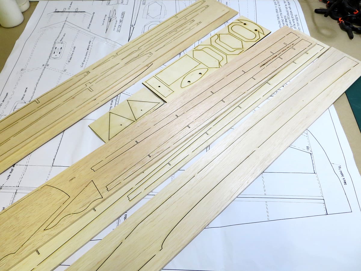
If you are going down the Sarik route then there are several options available: a basic laser cut pack, an additional wood pack and a short kit, which contains most of the wood parts required. As I had plenty of balsa strip and sheet in stock the basic laser cut pack was the best option.
Looking at the plan I decided to update the model. Originally it used one servo driving the ailerons via a Bowden cable link up and another servo for the separate elevator, plus a further servo for the rudder. Back then electronic mixing of controls was a rarity so mechanical mixers were the norm, but this system tended to introduce additional slop in the system.
Another reason, highlighted by Mike in his original article, was that mechanically mixed elevons tended to give too much pitch response but not enough aileron (this problem can effectively be dialled out using modern transmitters). To help reduce surface drag he designed the ailerons and elevators to be relatively large so that minimal throws would be required to achieve good control response. To simplify the controls, I decided to use elevons driven by a servo in each wing. The original internal rudder linkage worked well so there was no point in changing that.
As mentioned, my mate Rob generously offered to build the model. But I had an unusual pang of conscience, so I told him he could keep it if he would be prepared to build the kit version for me some time in the future. Rob is never one to turn down a good deal, so the answer was a resounding, ‘Yes!’
TIME TO BUILD

The wing is a good place to start because when complete it helps in the accurate construction of the fuselage. Fashion the front and rear wing spars first from 3/16” sheet and the control surface spars from 1/4” sheet (if scratch building), ensuring you don’t cut the angled rib notches deeper than 50 percent as this will weaken them.
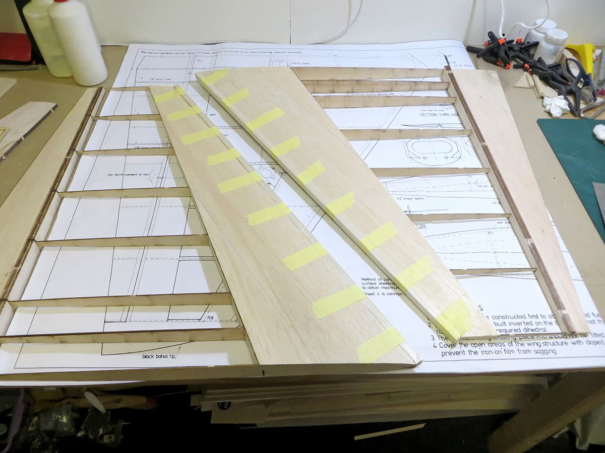
Tack glue the rear and control surface spars together, noting that these spars are deeper than required (see plan). This is intentional and acts as a jig, the excess being removed after the sheeting is completed. Building each panel separately, pin the spars inverted over the plan, adding all the ribs, and ensuring they are accurately positioned and vertical. Building this way gives the small amount of dihedral required due to the taper in the spars. Glue the spruce dummy leading edge in position and when dry remove from the building board. Now glue the left and right panels together inverted.
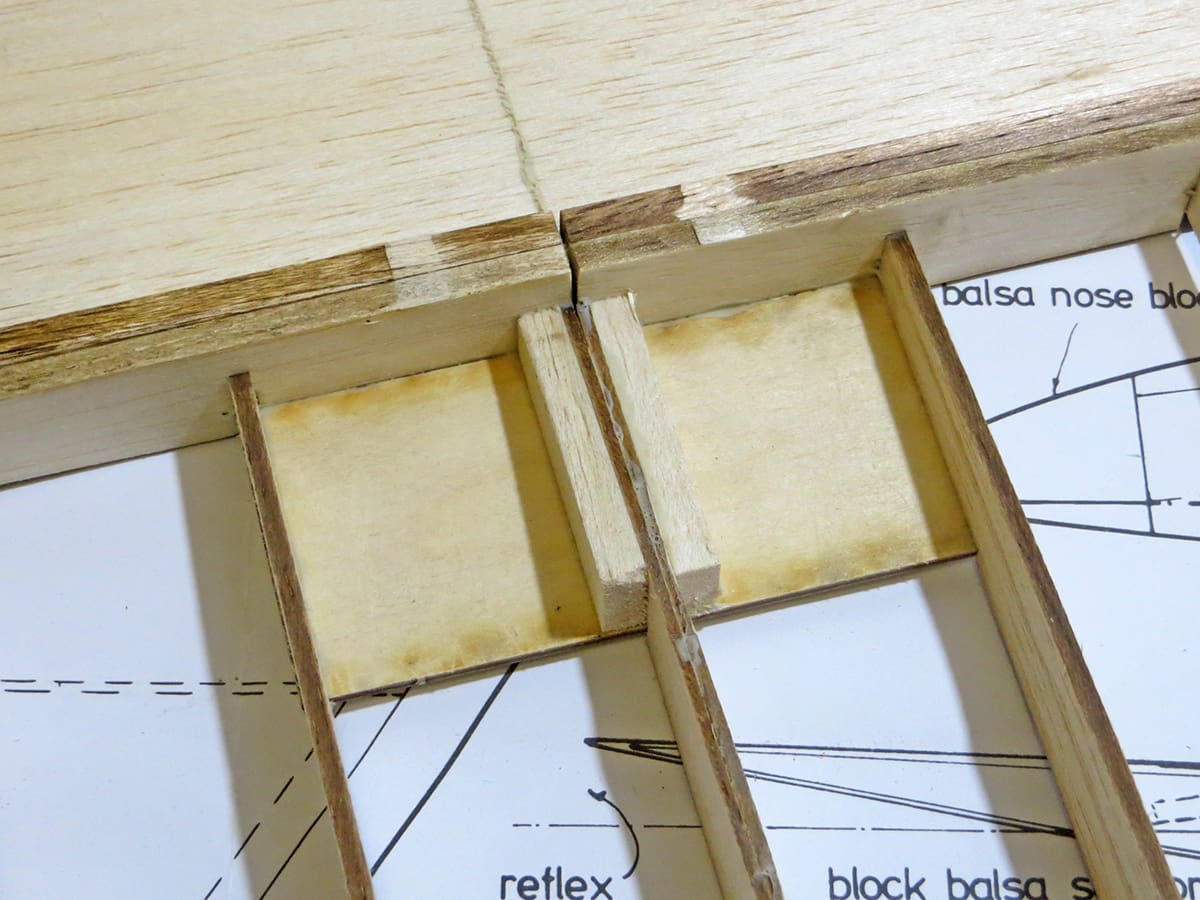
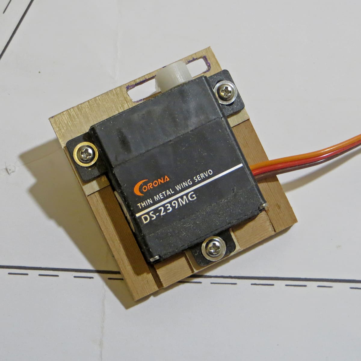
Prior to starting the 1/16” wing sheeting some thought needs to be given to the location of the elevon servos. The simplest and neatest solution is to use low profile wing servos, preferably metal geared due to the size of the elevons. Rob decided on Corona digital DS239MGs, or the analogue CS 239MG will do as an alternative. Mount these on 1/8” lite-ply bases, with slots cut for the output arms. Make up suitable servo boxes at the desired locations to screw these plates to (refer to the photos) and don’t forget to run the servo extension leads through the ribs prior to sheeting. Refer to the sketch on the plan as it shows the most economical way to use your precious 4” wide x 1/16” thick balsa sheet for the wing.
When you’ve sheeted one side add the elevon riblets and mark where to cut out these when the wings are finished, and add a hard point for the elevon horns. The plan shows the use of rib cap strips over part of the wing but if you fly from slopes covered in heather and bracken then feel free to sheet the whole wing; it will add little weight.
After fixing and shaping the 3/8” sheet leading edge, along with the tip blocks, give the whole wing a final sanding to remove any unwanted material. Trim off the front of the wing to accept R10, but don’t glue it in position. You can now cut out the elevons and sand the leading edges as detailed on the plan to allow correct movement.
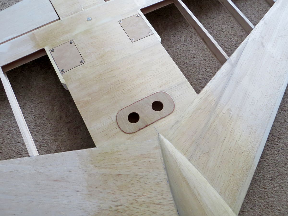
As the fuselage is quite a handful it is useful to cut two holes in the underside of the wing to help when launching but do add some reinforcement around these; 1/16” ply will be perfect.
FUSELAGE
This is a simple build. Start by cutting out the fuselage sides from 3/16” medium sheet then glue the medium 3/4” triangular stock along the top edge, forward of F2 and to the rear of F6 on the bottom, as detailed on the plan.
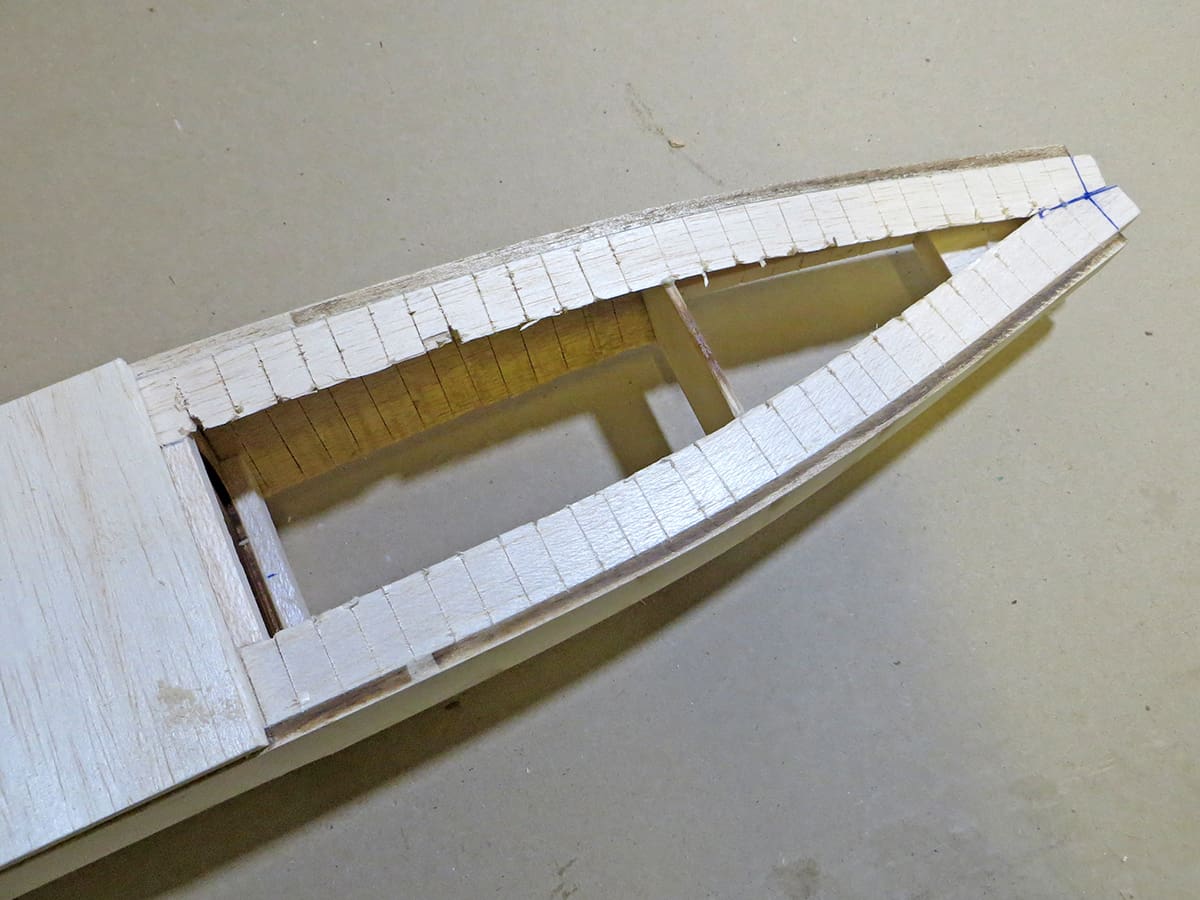
The fuselage nose section requires curving so to make this possible cut V slots into the triangular strip, top and bottom, forward of F2. Formers F1 to F5 are cut from 1/8” ply but only F2 needs to be traditional ply. The others can be lite ply, including R10. Assemble the fuselage, gluing formers F2 to F5 in position, ensuring accuracy, then add the 1/4” med. top using cross grained balsa from F2 to F5.
Whilst this is drying make the fin and rudder as shown.
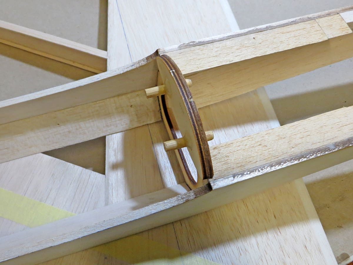
The fit of the fuselage to the wing needs checking and it may need some adjustment of the wing seat to make this perfect. When sorted glue R10 in position on the wing so the locating dowels align in F2.
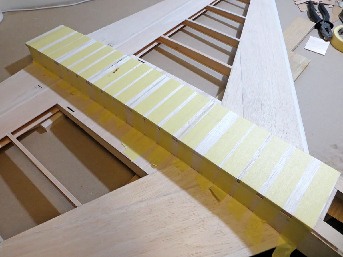
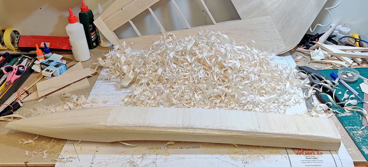
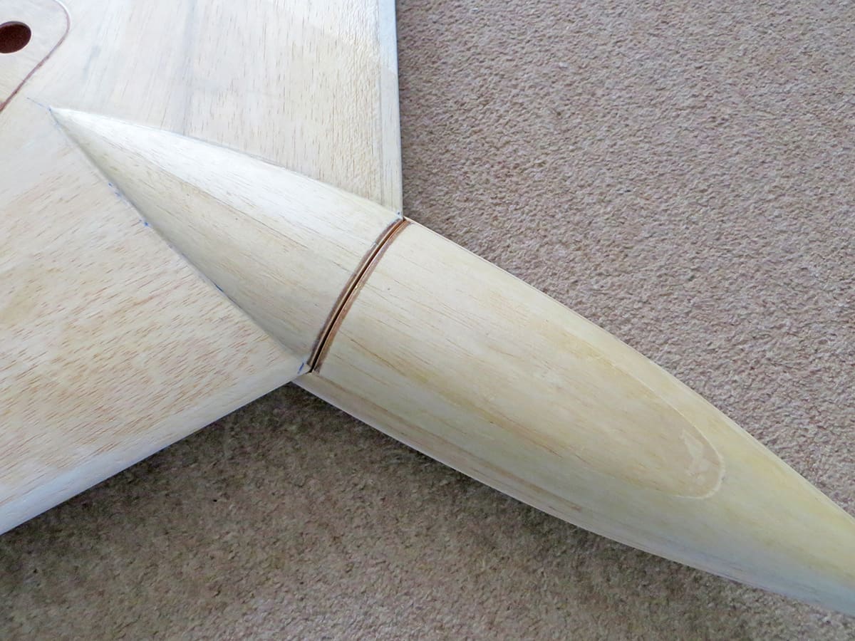
To form the curved nose section, dampen the external fuselage sides forward of F2, then pull in, holding temporarily in place with masking tape or rubber bands until dry to form the curve. Trim the triangular stock as necessary to fit the hard balsa nose block, then glue up using epoxy and again tape up to hold it in place. Also, before it sets, push F1 into position and glue.
After it has dried glue the top 1/2” and bottom 1/2” and 1/4” sheet in position. The fuselage is now almost complete other than shaping, sanding, and cutting the slot for the fin. I would also glue R9 in at this point to take the captive nut for the wing bolt. To get a perfect fit use epoxy to glue it in position, then assemble the wing onto the fuselage, align and tighten up until it has set.
FIN & RUDDER
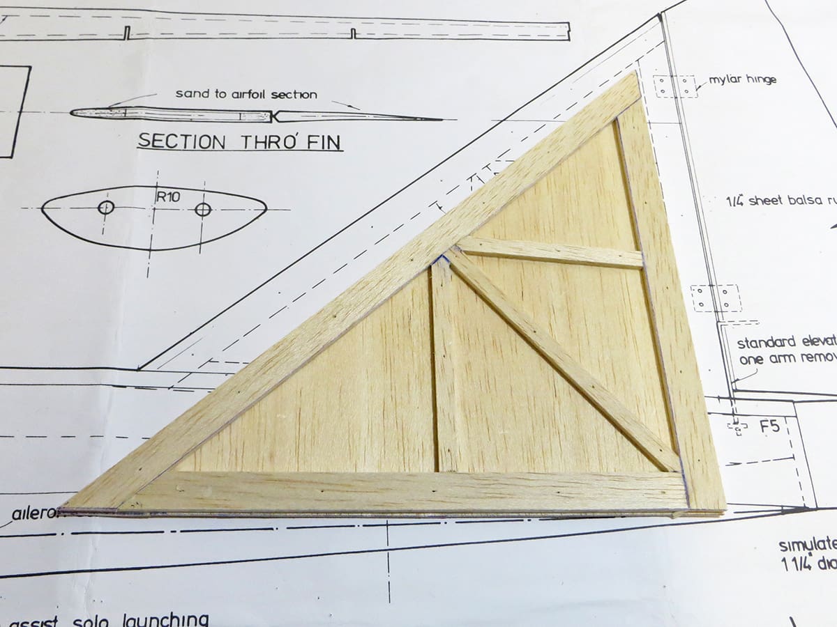
Although you could make the fin from sheet it takes just a few extra minutes to build the frame shown on the plan, which is light and strong. Use medium hard for the frame and medium for the fin sheeting and rudder.
Simply round the leading edge and taper the rudder at the trailing edge, but don’t get carried away and make it too thin! I would cover this before gluing to the fuselage as it’s easier to do. Mylar strips work fine as hinges; I use drafting film cut into strips.
COVERING

Film is the way to go, and my favourite is the type that was sold by HobbyKing but is now available from 4-Max in the UK for only £20.00 for five metres (at the time of writing) – an absolute bargain.
I’ve used this film for several years now and it’s superb. Almost impossible to burn through with a heat gun, and with incredible shrinkage, it seemingly never slackens off. It’s similar in thickness to the old Solarspan. I’ve used it on a 1/3rd scale Cub with no issues and even when the model was in 40 deg. C heat it didn’t slacken. I believe the translucent and chequer patterned versions are a little more expensive.
As designed the elevons are top hinged so the film will work for this as well, but I prefer to put a few Mylar hinges in too, just to be sure.
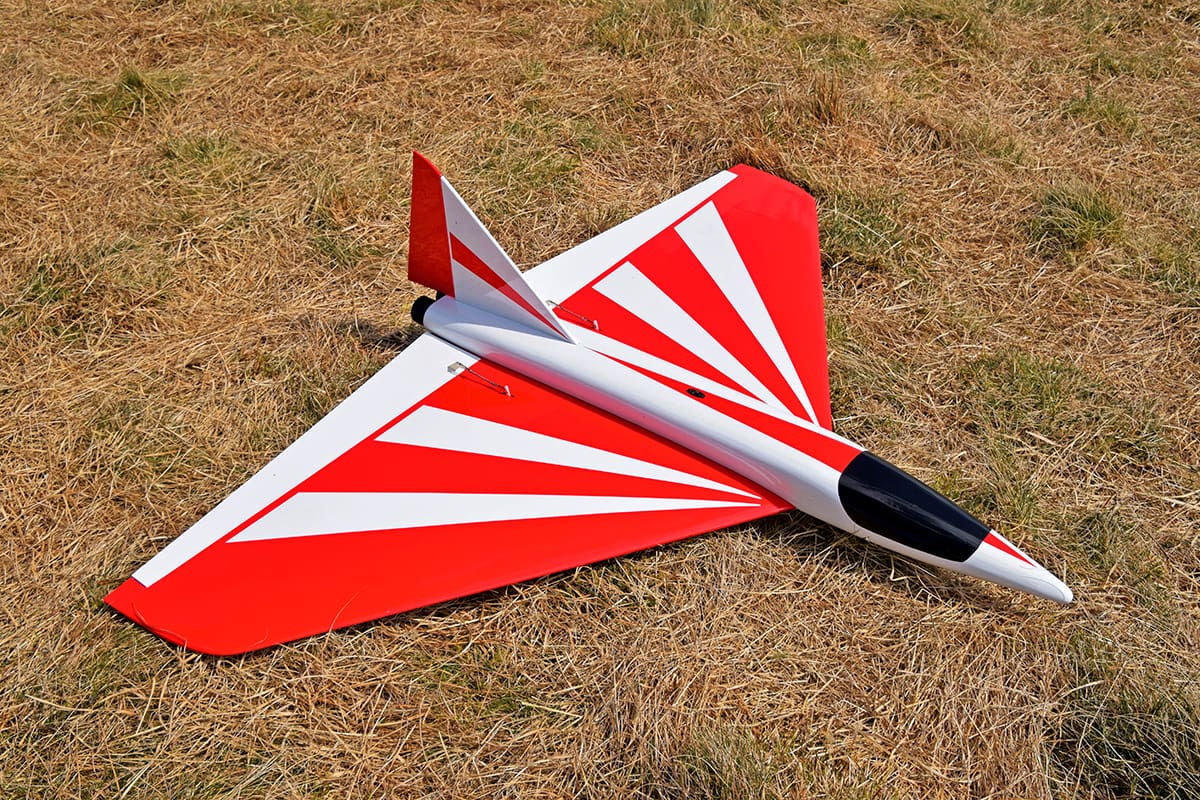
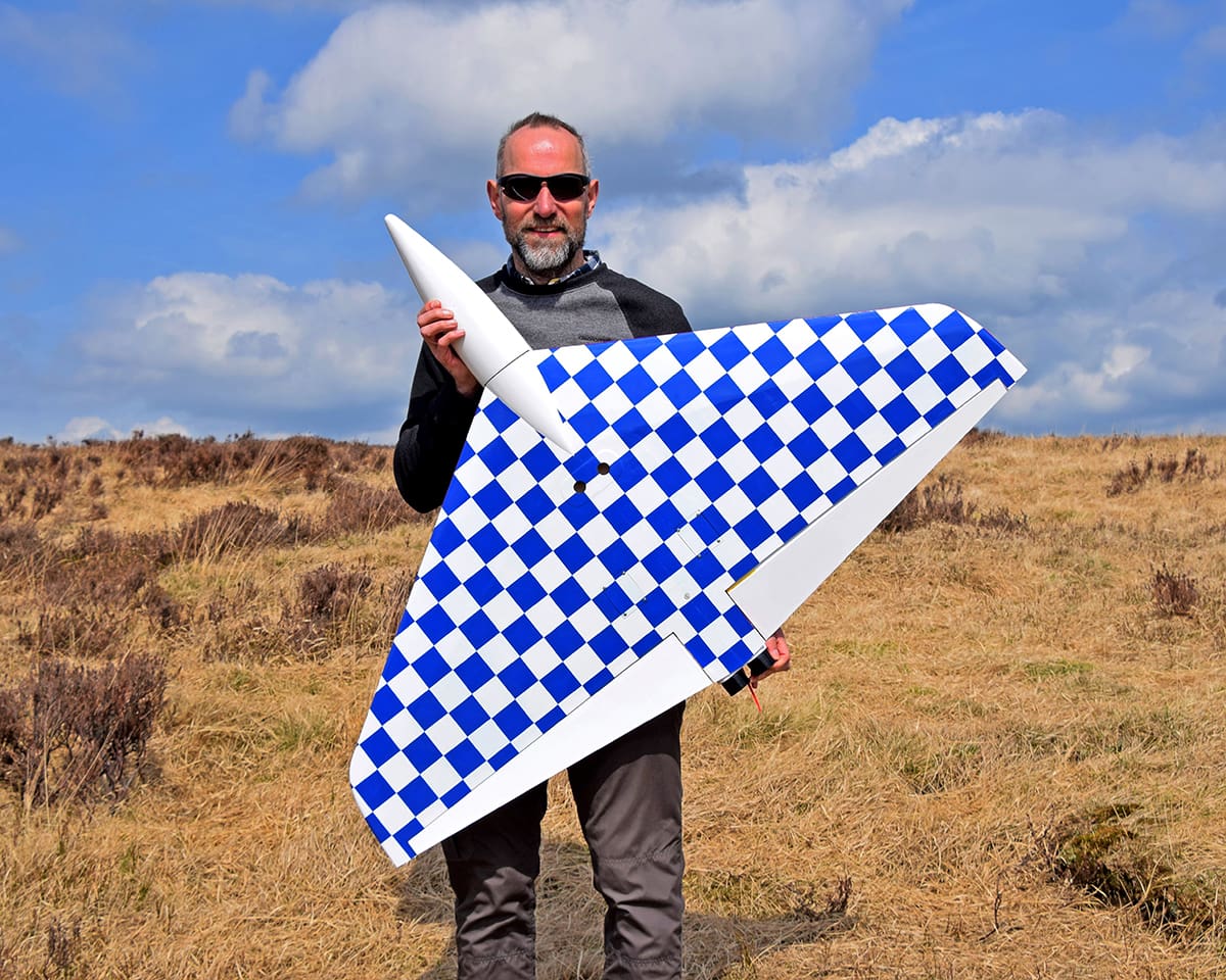
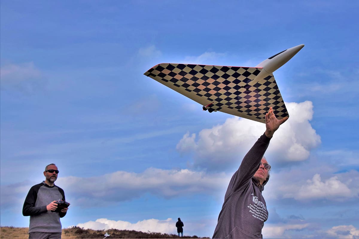
Choose a suitable colour scheme that helps orientate the model at distance. My preference is a dark solid or chequered underside, with a lighter top covering and contrasting trim flashes. This works for me in less-than-ideal light conditions, but Rob’s scheme, as shown in the photos, was good too.
RADIO GEAR
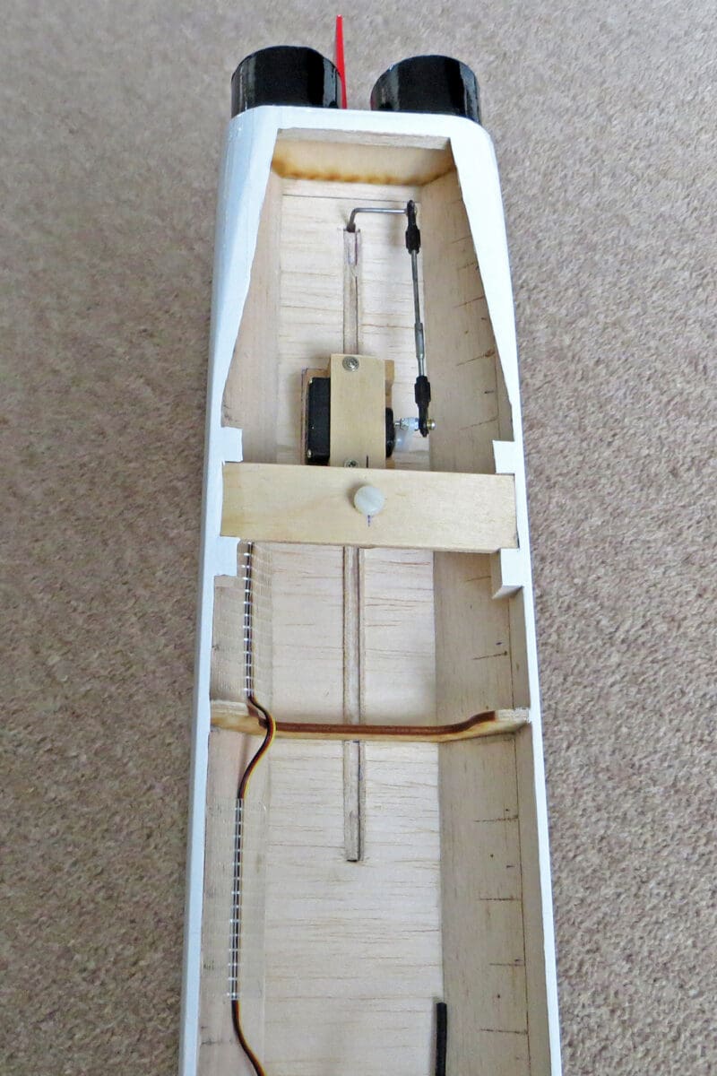
If you’ve decided to use the elevon solution detailed above, rather than the original separate elevator and ailerons, the install is simple. In practice the low-profile Corona servos have worked out well. But for the rudder I would use a midi sized metal geared servo as it’s a relatively large surface.
Position the battery to get the C of G correct and, for convenience, fit a switch to the fuselage. Use pushrods that won’t flex and metal quick links, along with decent quality horns.
TIME TO FLY
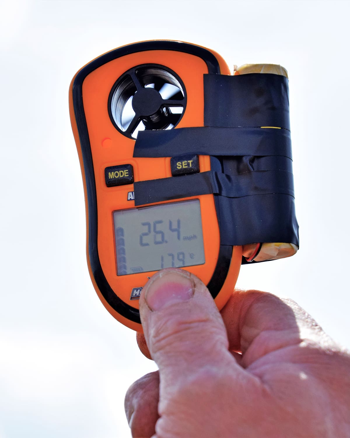
The original weighed approx. 2.5 lbs and with 5 sq. ft. of wing area, the wing loading is around 8 oz. per sq. foot. That’s unusually light for an aerobatic soarer, but don’t let this bother you as it’s a slippery thing with very low drag and as mentioned its good for flying in wind speeds between 10 – 50mph without adding any ballast.
Make sure the C of G is as shown on the plan for the test flights. You can play around with the balance point to suit your preference but remember, as the C of G moves rearward less reflex is required, so less drag and potentially more speed. But over egg this and your Delta Lady will become unpleasant to fly and may even be unstable.
We also found it necessary to half the reflex indicated on the plan when using full span elevons, reducing it to 1/4”. But, as mentioned, this is dependent on your C of G position.
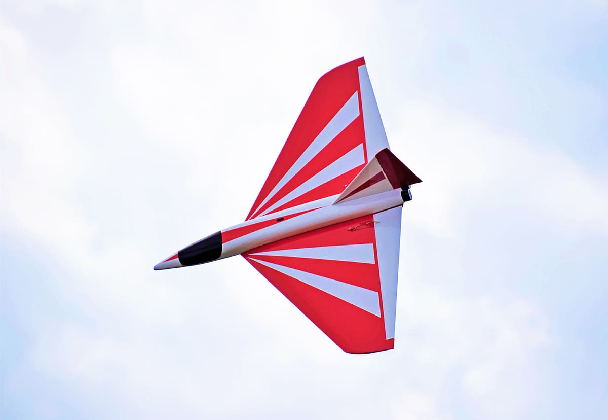
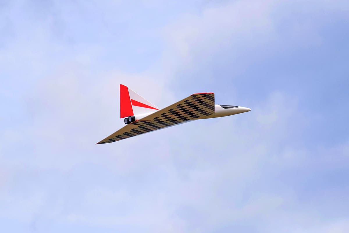
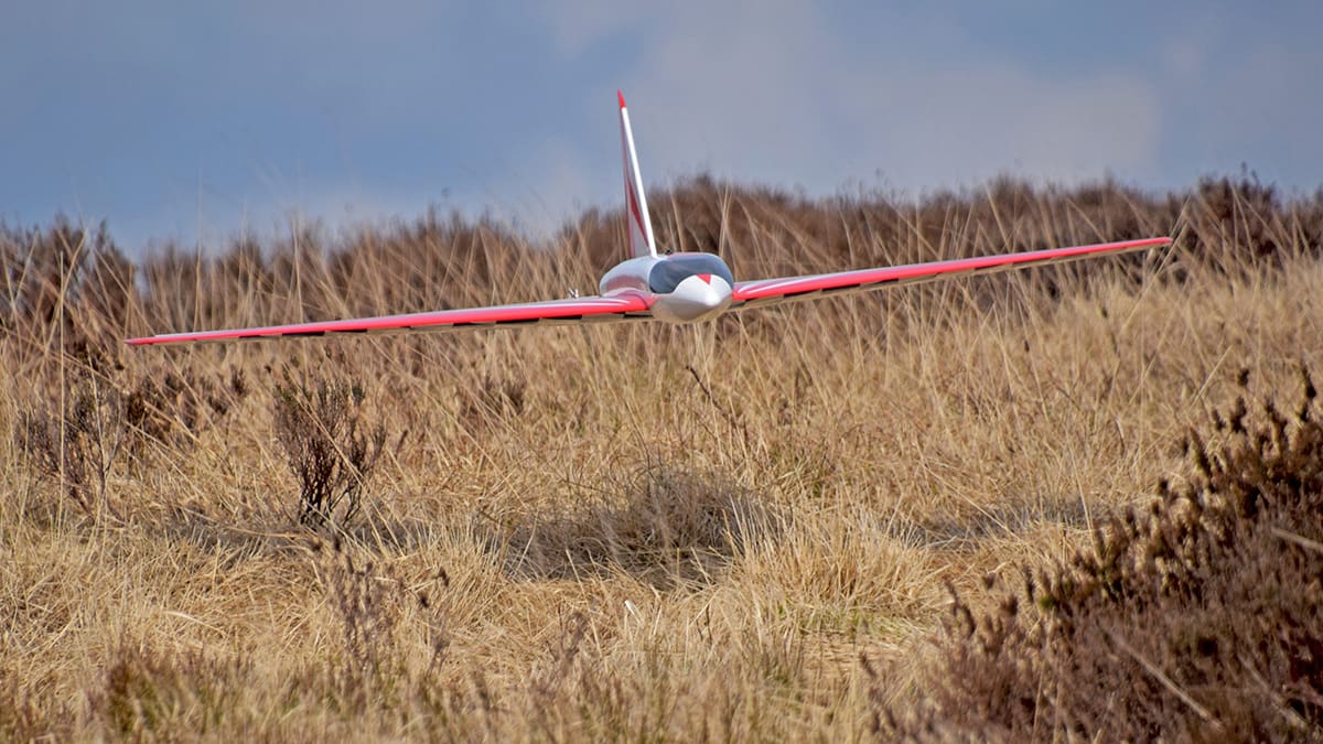
The model is an absolute peach to fly. It’s almost a universal sloper, capable of floating around at the bottom end of the envelope whilst behaving like a hooligan when the wind ramps up. It will do many aerobatic manoeuvres (except for knife edge) – loops, rolls, bunts, inverted and even ungainly rolling circles.
I can’t convey how great I think this model is. But one thing’s for certain, I’m always going to have one in the slope fleet from now on.
Laser cut parts and additional items are available from Sarik Hobbies:
DATAFILE
Name: Delta Lady
Model type: Sport aerobatic delta
Designed by: Mike Trew
Wingspan: 1372 mm (54”)
Reflex: 6.3 mm(1/4”)
Flying weight: 1.13 kg (2.5 lbs)
Wing loading: 8 oz/ft2
Functions (servos): Elevons (2), Rudder (1)