
It’s difficult to believe that the DHC-2 Beaver was built and produced just a couple of years after World War II and of the 1600-odd examples built, there are still several hundred still flying, from mostly-original classics to much-modified up-to-date aircraft. The type is steeped in history, having provided the US Army Air Corps with a long-term and very versatile operational platform, whilst others have served businesses and individuals as an all-terrain, STOL machine unrivalled in its capabilities for many years; an RNZAF example famously supported Sir Edmund Hillary’s expedition to the South Pole.
E-FLITE ARF DHC-2 BEAVER 2e
Whilst i.c. models of the Beaver have appeared in kit form over the years, E-flite are amongst the first ARTF manufacturers to produce a decent sized electric kit, and what a kit it is – the Platinum Series badge is entirely appropriate.
Enjoy more RCM&E Magazine reading every month.
Click here to subscribe & save.
From initial examination of the many components you immediately see the difference from the compromised ARTFs we have been inundated with over recent years; not only are the main structures and panels beautifully made and covered in a classic Beaver livery, the hardware, accessories and instructions are the best quality I have ever seen. Someone has finally decided to do the job properly – Hallelujah!
The wings have their ailerons and flaps pre-hinged, complete with all the ridge details etc., the fuselage comes with the beautifully fitting access hatch already sorted out with the most powerful magnets I’ve come across, the undercarriage is both scale and sturdy and attaches for once to a suitably strong piece of fuselage structure, and the superb quality cowl has an insert replicating a Pratt & Whitney WASP radial engine.
With a 68” (1.75m) span and with a chunky 43” (1.1m) long fuselage, this is a club size model by anyone’s standards at just smaller than 1/8th scale and is a demonstration to seasoned i.c. flyers that electric flight’s relentless progress continues at one heck of a pace. Although an ARTF, there is still a good bit of work to do to bring this model to airworthiness, although none of the steps are beyond anyone with a little airframe assembly experience: even fitting the recommended powertrain is a doddle.
FUSELAGE ASSEMBLY
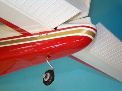
On a model of this stature it’s best to stick to the instructions and assembly begins with the attachment of the main undercarriage legs. These should slide into their respective slots secured by four Allen bolts: in reality to get the pre-drilled holes to correspond to the blind nuts you will have to at least enlarge them or at worst elongate them – you will also need quite a long driver for this as the fuselage is deep (and they are located beneath a tray with several cutouts). Sadly, due to the way the right leg had been manufactured, despite all efforts there was still an unsightly gap between the fairing and the fuselage side – this was a shame as the left one fitted superbly.
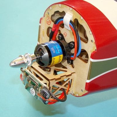
Motor mounting is next, so it is worth pointing out that two different powertrains are available with this model, a Power 25 set for flying from land and a Power 32 set for use with floats. I decided to use the smaller 25 size set as I had seen video footage of the model on YouTube suggesting that even the smaller set-up would give ample power for my purposes, although this would lead to some unexpected problems.
A clever innovation when fitting the motor is that the blind nuts in the firewall can move within slots to whatever position your chosen radial mount might require, which takes away the frustration of having to modify anything.
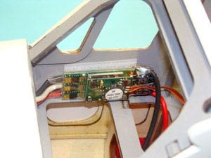
The ESC is shown attached to the front of the battery box with all the wiring secured to the firewall clear of the outrunner’s rear rotating can; once this has been done the cowling can be fitted but not before painting the various dummy cylinder parts and cutting away the material between them, as this is essential for cooling airflow. However, with the finished dummy cylinder moulding glued into the cowl, it was impossible to fit the cowl due to the thickness of the ESC. This was easily remedied by re-routing the wiring to fit the ESC inside the fuselage and being a 60-Amp unit that was unlikely to be handling any more than 40 Amps, the reduced cooling airflow didn’t threaten to be a major issue.
MORE FUN AND GAMES…
Sadly, this wasn’t the only oversight at the front of the model; the fun and games continued with several unsuccessful attempts to bolt the cowl in place using the four Allen bolts supplied. As the lugs are a good three inches deep into the cowl, it soon became clear I would need a rather long “ball wrench” type Allen driver simply to reach the bolts, and not having such a tool I sent off for one specially. When it arrived, I spent over two hours unsuccessfully trying to get more than one bolt properly located and tightened – partly due to the extremely awkward angle the bolts are (in relation to the access through the front of the cowl) and partly due to limited space between the dummy cylinders, even though the plastic between them had been removed as shown: I could only conclude that the lugs and the blind nuts in the firewall didn’t match up very well.
When I realised almost a full evening had been taken up unsuccessfully securing a cowl that should have taken a few minutes, I did what I imagine anyone buying this model will do, and that is to partially secure the cowl by the single bolt out of four that did line up, and tape it firmly in place all the way round with some invisible tape. Not the ideal solution.
You may well think that the front of the model had caused enough problems by now, but worse was to come when I tried to fit the prop using the supplied adapter. For some reason the motor spindle didn’t protrude out from the hub far enough to push the adapter on enough for it to grip the shaft securely, and even pushed on as far on as possible the blades of the prop were hard up against the cowl perimeter so the prop wouldn’t turn anyway.
What I had to do to sort this out was to buy a much longer prop adapter, pictured here in comparison with the supplied item, that gave about an extra half of an inch (12mm) length; this allowed the prop to have enough clearance from the cowl to both turn and look right. With hindsight I would imagine this error has probably occurred by the front end components being designed for the fitment of the larger POWER 32 motor, the output shaft of which will naturally stick out a good bit further due to its thicker armature, when the supplied adapter will do the intended job. A good quality plastic spinner is also supplied but I omitted this from the finished model as it made it look a little too 'modern' if you understand what I mean.
ONWARDS AND UPWARDS…
One thing I usually hate about ARTFs is having to cut away the film from the fin and rudder to expose some wood for the glue to work properly, but the instructions suggest doing this with a soldering iron so as not to cut into the balsa and subsequently weaken it! Lo and behold, I fitted my smallest, most pointy soldering bit, turned the heat up to 400 degrees and it worked a treat – although I did err a few millimetres inside my drawn line just in case! Useful little bits of advice such as this really make a difference and I will use this method from now on as it is far less damaging to the surrounding balsa than a scalpel.
A removable panel at the rear of the model makes fitting and gluing the tailplane into position much less messy than usual, and also conceals the rudder, elevator and steerable tailwheel linkages keeping the exterior true to scale, the rudder being operated by means of a vertical rod with a flat on it for the control horn’s grub screw to locate with.
However there was one rather obvious mistake here as when set up exactly as described in the instructions, ALL the control horns ended up on one side when the pushrods emerge from opposite sides. You can’t actually do much about this as the horns only have the grub screw accessible from one side, i.e. from the rear of the model. The answer is to invert one control horn so it can be secured 180-degrees round the vertical rod, but this does mean it no longer lines up exactly with the pushrod exit so it will need a kink bent in to work effectively.
Do remember that the tail should not be fitted until the wing has been completed and bolted in place, as it is required for the wingtip to tail tip lengths. Fitting the windows using canopy glue concludes the fuselage assembly, although had this not been a review model I would almost certainly have added the nice looking but optional cockpit kit and pilot torsos which are available at extra cost just to give it that added touch of realism.
WING ASSEMBLY
When it comes to wing assembly, joining the two panels is simplicity itself; but the aileron and flap servo and linkage installation is extremely important and therefore will take up a good bit of time and concentration. Again the excellent instruction manual has everything covered and the pictures, although in black and white, are very clear – it even tells you how many and what length of extension leads you will need. Pull strings are already installed to pull these through but as usual it is important to tape the servo lead plugs into their extension lead sockets as they are prone to pulling apart whilst feeding through the wing structure.
The flap servos and linkages are completely concealed and very well designed, in fact I only needed to adjust the ATV on the flap function a smidge to counter the millimetre of over-travel that can make a servo buzz annoyingly (this also consumes unnecessary power and can burn out a servo in time!).
The ailerons have the only externally visible linkage on the whole model, operating the surfaces by means of a pushrod, although again cleverly designed covers only allow the output arm and pushrod to be seen, and this is underneath after all. The excellent quality hardware, along with a very good fit between the servo covers and the wing leaves you with finished panels that have very precise linkages and little ugly looking paraphernalia underneath.
For some reason my kit had a pair of thinner wing joiners (with the specified dihedral built in) rather than the single thicker piece shown in the instructions but nevertheless they fitted well.
FINAL SET-UP
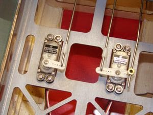
As the motor was fitted during the fuselage construction and the aileron and flap servos had to be installed and tested before the wing panels were joined, all that remains is to fit the rudder and elevator servos and set up their respective linkages. The elevator and rudder each use a lengthy pushrod to their quite large surfaces, so it was clear that whilst cheap 9-gram micro servos were sufficient for aileron and flap operation, larger units would be needed here. I ended up going for a pair of powerful Supertec PARK HPX midi size servos – the servo apertures in the Beaver fuselage may as well have been made for them. All supplied hardware was very strong, and the resultant linkages were all precise and smooth.
With the recommended 12 x 8 prop fitted (I used a JFX wooden prop) I connected the ESC plug to the 3s 3700 ma/h Li-Po to take some power readings. For the statisticians, full power consumed 400 watts, meaning that the Li-Po was operating at around 10C, well within the 20C pack’s comfort zone and unlikely to be demanded for any length of time. This gave the model a power to weight ratio of 90 watts per pound, which for a model of its type is entirely appropriate, despite using the smaller 25 motor.
FLYING THE BEAVER!
When it comes to the Centre of gravity, further evidence of this model being designed around the larger Power 32 powerplant and 4s Li-Po. The instructions suggest a 3200 mAh 3s Li-Po in conjunction with the smaller 25 motor, but with this arrangement the model was behind the specified “57 – 70mm from leading edge” point, which is why I used a 3700 mAh pack that brought it just within the range, at 69mm from the leading edge.
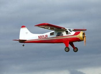
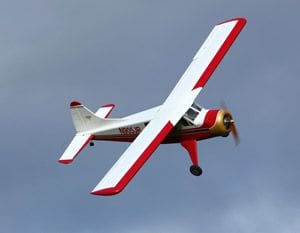
Weighing 4 lbs 4 oz (just under 2kg) ready to fly, this large and very pleasing model looked absolutely superb and without a nicely mown grass strip at our disposal but a lovely sunny morning we were very excited at the prospect of a hand-launch test-flight and photoshoot. At full chat and with a good positive lob, the Beaver was airborne and gaining height quite steeply, with a good few clicks of down elevator required to counter the enthusiastic climb rate.
After a circuit of further trimming, we soon had her flying straight and level but to be honest the Beaver was flying awfully, with a horrible pitch-up and adverse yaw when ailerons alone were applied, and a good bit of rudder and down elevator necessary to make the turns look decent. When Peter (who is responsible for the superb flying shots in this review) suggested dialling in some flap, the model settled down considerably and became much more flyable, although about 30-degrees of flap was required – suggesting that the rearward C of G range doesn’t suit the model very well at all.
After collecting the flying shots and an uneventful landing, the model was taken home for a re-think of the C of G position; given the flight characteristics at 69mm from the leading edge, lead weight was added to bring it 9mm further forward to 60mm, and this required 6 oz of lead, raising the model’s overall weight to 4 lbs 10 ounces (2100 grams) although this is still extremely light for a model of this size.
DONE AND DUSTED
Following the second launch it immediately became obvious that despite the relatively small shift in C of G, the effect was dramatic (possibly due to the relatively thin chord) and the Beaver was completely different to fly, the horrible pitch-up and adverse yaw when aileron is applied had all but gone, although this is still clearly a model that requires rudder in turns, but this could easily be mixed in if you struggle with rudder control. The extra weight is virtually unnoticeable and for what looks like a tiny little motor for a large model such as this, there was certainly no lack of power and level cruise was possible at just less than half throttle. At full chat the speed is quite surprising with an energetic climb rate, and bursts of this allow decent size loops and stall turns.
The model will roll quite well, although inverted flight requires most of the available down elevator stick, with the revised C of G; although this is a non-scale thing to do anyway.
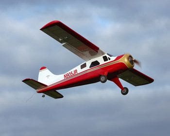
Where the Beaver excels however is with full-flap 'escalator' type approaches, slow fly-bys, side-slipping, touch and goes etc. where you get to appreciate the close-in predictability of the design. With loads of power available to get you out of trouble and little chance of getting anywhere near the stall unless you are really pushing it, the Beaver is a joy to operate and as you can see from the flying shots it looks absolutely fantastic too; one of the nicest looking models I have ever had the pleasure of reviewing.
EAGER BEAVER
Considerable thought has clearly gone into this model, and it occurred to me at this final stage that it was a great shame about the ugly gap between the right undercarriage leg and the fuselage, the anomaly with the rear end control horns and the various oversights at the front of the model; without these it would surely be a near-perfect product and the quality of production is superb.
Naturally quality like this comes at a price, but at less than £150 if you shop around a bit, the value of this kit is also very good. Only a few years ago, test flying a model of this size would have been the arguably stressful conclusion of several weeks if not months of shopping around, building and covering – and the financial input certainly would be no less than this. In comparison, this Platinum Series kit brings you a fine model built and covered (in genuine Ultracote) to an extremely high standard that can be assembled and set up in a weekend at the longest despite the usual frustrations and required alterations.
The recommended Power 25 motor isn’t the cheapest, but it is perfectly suited to the job (as long as you buy a longer adapter) and has been completely reliable and although designed for a 3200 3s Li-Po I would recommend using the largest and heaviest Li-Po you can physically fit in the aperture to help achieve the C of G which seems to be best at around the 60mm mark: with my 3700 ma/h pack, flight times of over 15 minutes have been achieved.
In conclusion, whilst ARTFs are available by the dozen, if you’re prepared to spend a little bit more on them the end product is often well worth it and the E-Flite DHC-2 Beaver 25e is a first class example of this. Well designed, beautifully built and covered and with only a few assembly issues it flies well on a relatively small motor and never ceases to impress and entertain. Without doubt one of the best products of its kind I have seen.
By the way, as a follow up to this review I'll be looking at E-flite's float set that the model is designed to accept and flying the model from water so look out for that soon. (to be published at modelflying.co.uk 15/11/10 – ed).
DATAFILE
Name: DHC-2 Beaver
Model type: Scale ARTF
Manufactured by: E-flite, Platinum Series.
UK distributor: Horizon Hobby UK, www.horizonhobby.co.uk
Typical price: £145
Wingspan: 68" (1735mm)
Power system reqt's: Power 25 – 32 outrunner
Functions (servos): Ailerons (2), elevator (1), rudder (1), flaps (2), throttle via ESC.


