Keith Beaumont describes his rig for comparing the static thrust of model internal combustion engines
words & photos > Keith Beaumont
I enjoy making and refurbishing model IC engines. To me, it takes a lot to beat the sound of a recently completed engine starting for the first time, or after the re-build of a classic engine that probably has not been used for some 40 years. My model flying days are long gone, so all my engines are ‘test bed’ items.
Enjoy more RCM&E Magazine reading every month.
Click here to subscribe & save.
My standard procedure with a new engine, after initial start-up, is to go through the run-in procedure, then try it with different propellers and settings, while recording the RPM for each setting. After about a total run time of an hour, I find my interest for that engine tapers off and I then clean it up and mount it on a stand for display.
Some years ago, at an exhibition, I remember seeing a rather complicated rig for testing the static thrust of a model IC engine under power. It had a lot of levers and bell-cranks to couple up to a vertical Salter spring balance. Remembering this gave me the idea of trying to make one using more modern materials, to enable me to add another dimension to my testing methods.
I had recently made a five-drawer cabinet, on castors, with a flat top to accommodate a surface plate. The drawers are all mounted on double extension ball bearing sliders, and I had a pair spare. These gave me an opportunity to make a quick mock up of a test rig, at the same time trying to couple it to a digital luggage scale that I also had. Using just hand pressure to load the scale, the mock up showed that I would be able to measure forward load, but I needed to take some of the wobble out of the set up on a final design.
I will not provide exact sizes of the complete rig, as anyone who wishes to make something similar only needs the photos to see what is needed. Most of it is simple woodwork. I will explain the parts that I found important to make it a workable unit.
PARTS LIST
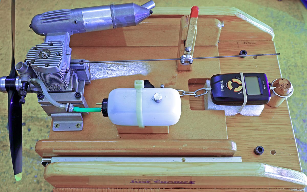
After a few quick sketches of what I had in mind, I drew up a basic list of what was needed. The moving part of the rig (I will call this The Deck from now on) would be very similar to my fixed one, normally held in a Workmate clone. It would need space to mount the Enya type engine mount, the fuel tank, plus a lever for adjusting the throttle on engines so equipped. I decided that, for safety, the forward movement must be totally restricted at some point and that this could also double as a lock down point for use when not measuring forward thrust. Also, there would need to be a means of coupling the digital scale that was easily removable.
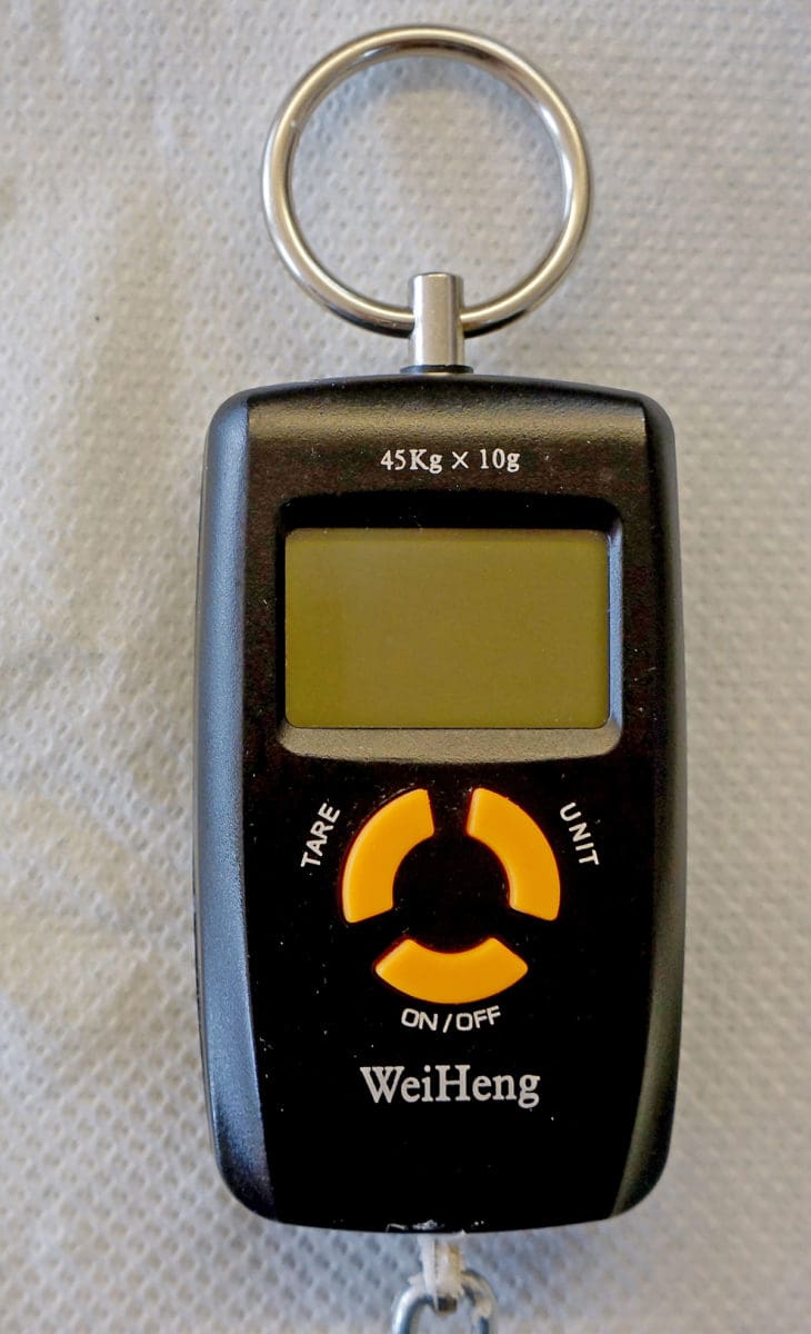
The drawer runners I had were not top quality, so I did a search and decided on a pair of Hafele stainless steel items of basic 250 mm length. I could not find single extension runners of this size and settled for the double extension type that I modified on assembly. The luggage scale I had was considered too large and I purchased a smaller item from Amazon, designed for weighing fish, with a lower weight range, in the belief that the lower figures will be more accurate. (Photo 2)
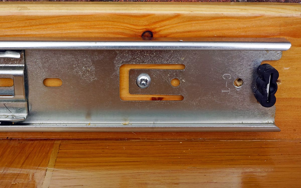
The fixed part of the rig (I will call this The Base) would be very similar to the bottom drawer position of a cabinet, with a length able to accommodate the Deck. To keep the Deck as short as possible and to accommodate the length of the runners, I cut an area out of this to allow the digital scale to be at a comfortable distance, so that I can see it easily when running an engine. (Photo 3)

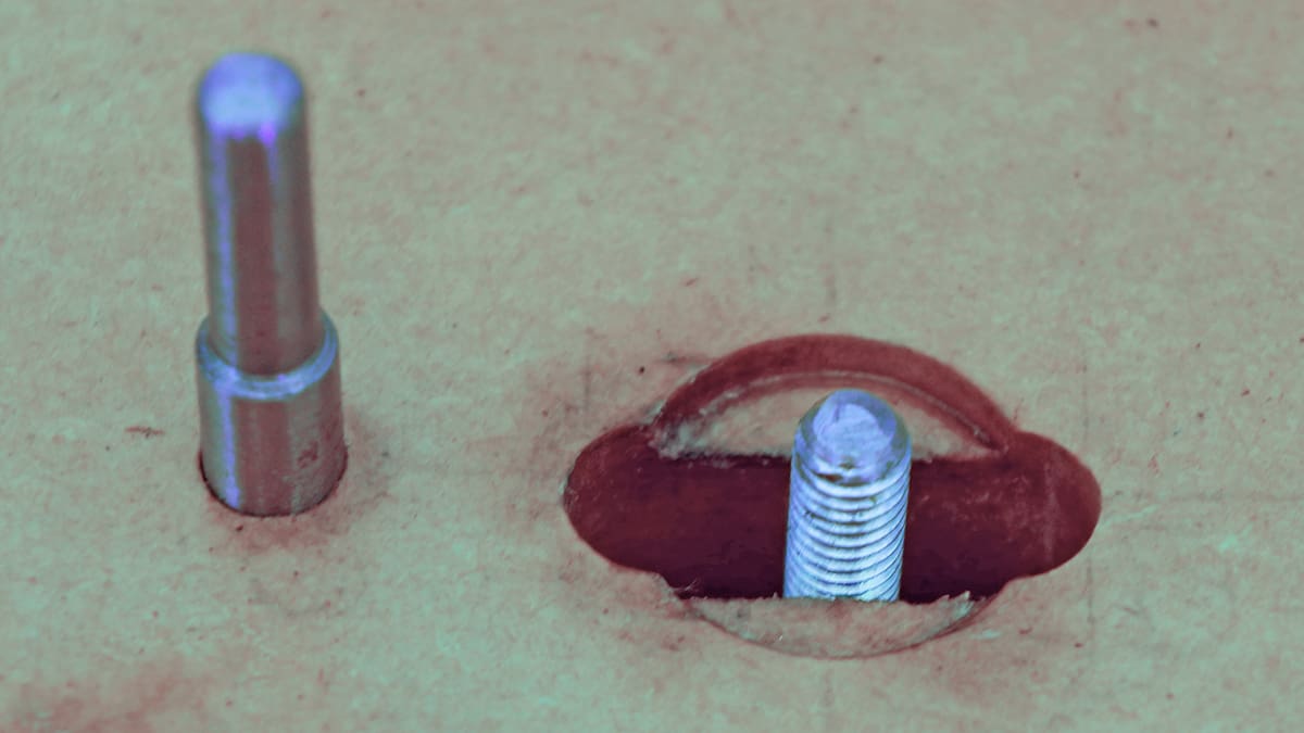
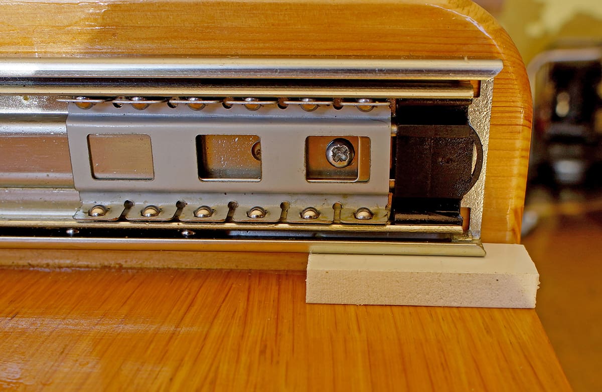
To restrict forward movement, as a safety feature, a slot was routed on the centre line 1-1/2” long to clear a 6mm bolt fixed in the Base; this protrudes through the slot in the Deck and is long enough to allow a 6mm knob to screw down. (Photo 4)
The plastic headed knob I used has a 3/8” deep x 3/4” diameter circular portion below the grip so a 1/8” deep counterbore for this to fit in was drilled in the centre of the slot. When screwed down it gives a positive lock to any movement of the Deck.
It was obvious that, to ensure forward movement is as friction free as possible and with minimum sideplay, the Deck must fit accurately between its supporting side walls. Its width had been determined by my mock up and in my case is 10 inches inside these. The bottom plate and side walls were made from 12mm MDF. Having checked the width of the bottom plate to be parallel to within .010”, a 12mm wide x 1/8” deep recess was routed down each side to bed the side walls in. Sidewall height is determined by the depth of the drawer runners, plus the space under the Deck plate, plus 1/2” to allow the top edge to be radiused. In my case this is 3-1/2”. To make the appearance ‘softer’, radii were applied to all the edges. PVA adhesive was then applied to the routed recesses and the side walls rubbed in and gently clamped, checking for correct 90-degree alignment at the same time. When the PVA had set, the clamps were removed and three CSK screws per side were fixed from underneath into the sidewalls. The outer faces were then cleaned of PVA surplus and checked for 90 degrees.
KEEP ON RUNNING
At his stage it is a good idea to acquaint yourself with the Hafele runners as no instructions come with them. The first thing is to know how to separate the moving part from the fixed so that they can be screwed to their respective wall. Photo 5 shows the black plastic lever that must be lifted up to allow separation.
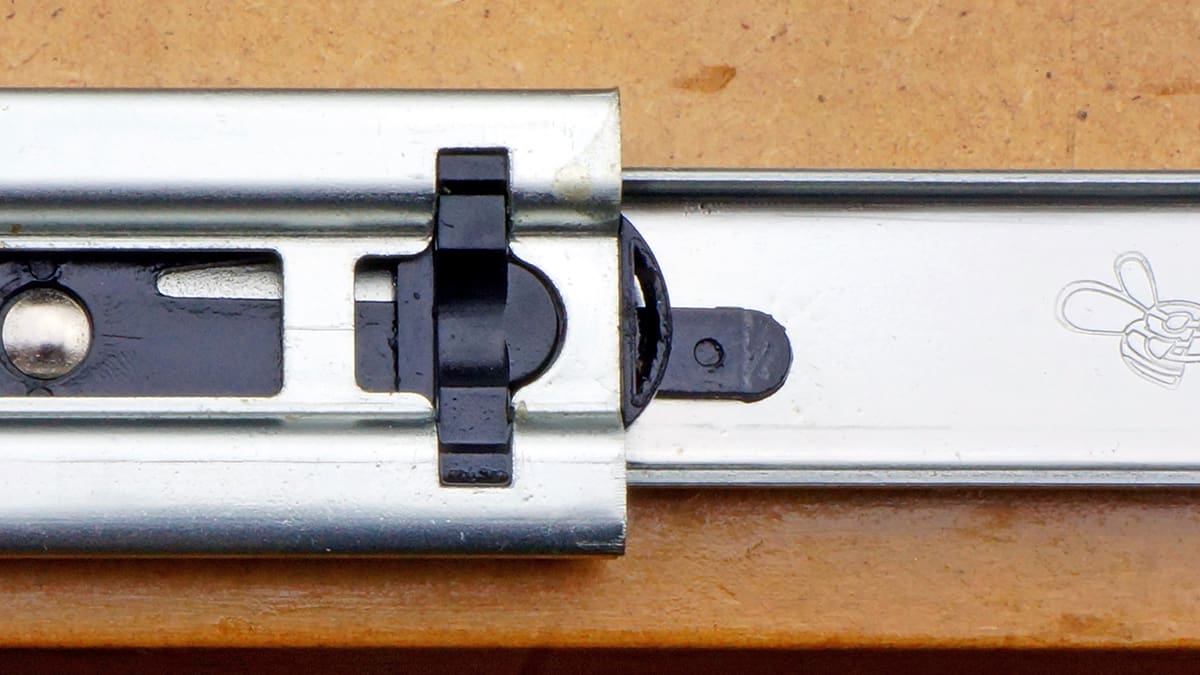
When the runners are fixed in position, be advised that one will be moved up and the opposite moved down. The other thing to note is the fixing holes, of which there are several. The idea is to achieve minimum friction, so the balls need to run in the centre of the channel, without touching the sides. To achieve this two of the holes are within a tab that can be bent inwards to fine-tune the width. (Photo 6)
To determine the inside measurement of the Base sidewalls, I taped the runners to the Deck walls temporarily to measure the total width. To this dimension I added 1/16”. This will then allow some adjustment using the tab fixing. One side only needs the tabs to be bent inwards. The other side can be screwed on flat to the surface.
Having determined the width of the Deck, I was able to decide on the final width and length of the Base size. In my case I decided 14” was about right for length. I had a couple of old kitchen cabinet doors that are oak faced MDF and were long enough, as well as being about right for width. The side edges had a smooth radius, so I left those on, and having decided the total width of the Deck, I used some 1/2” thickness pine from another old door to make the fixed sidewalls for the Base. I shaped the profile and radiused all edges to give it some shape. The width of the oak faced door was 1/2” wider than the total width of the Deck, plus runners, plus sidewalls. So, two 1/2” wide parallel grooves 1/8” deep were routed along the length to give an internal dimension to match this. A similar bonding procedure was used to mount these sidewalls to the base plate.
After clean-up and a check to confirm things were at 90 degrees, I now had what was, in effect, the bottom of a drawer cabinet. I then marked the position for the 6mm bolt that would be the safety retaining stud, on the centre line, to pass through the hole in the Deck. I used a mushroom head roofing bolt for this, drilling 5mm diameter through the MDF, and with a shallow counter bore on the under side to keep the head just below flush. This screwed through the MDF, aided by a touch of silicone grease, and was then removed to wait final fixing.
The runners were then separated into their two parts ready for screwing to their respective walls. At this point one side needs the fixing tabs to be pushed outwards about 1/16”. I chose the left side. The procedure is to fit the moving part with the ball bearings to the outside of the Deck each side. To ensure these will be parallel to the base the deck was placed on a flat surface and a 3/8” thickness spacer was used to align the runners while screwing them into position. The front edges being placed at the front edge of the Deck walls. (Photo 7)
With the two runners screwed in place on the Deck, we now need to replace both the outer tracks onto each inner part, now screwed to the Deck. This assembly was then placed into the Base and should be a good fit between the Base walls. To give some clearance underneath the Deck, I placed it on a piece of 7mm MDF to raise it off the Base, while screwing the outer track to the Base side walls. To find the fixing holes requires the Deck to be pushed in and out in order that the access holes line up. The right-hand track was then screwed flush using plain holes at each end. Similar juggling is then needed to get access to the two tabs on the left-hand side. After screwing through these and removing the 7mm MDF the deck should be able to be slide forward and back, smoothly and without any sideways movement. At this point it is worth eyeing up each track from the front to check the balls are running in the centre of the track. Fine adjustment is then available through the left side tabs, by either sliding, say, a steel rule between the sidewall and the track and gently easing the track over, or, if movement is required in the other direction, gently squeezing the track to the side wall by hand. Moving the Deck forward and back several times helps to settle in the movement.
At this point I decided to see if I could measure the friction load needed to ‘unstick’ the Deck to begin movement. To do this I put a pin into the Deck near the front edge and coupled the Digital scale hook to the pin. Pulling the scale gently forward and observing the reading at the same time, I got a reading of 1/2 oz before the Deck moved. I considered this a good result and not something that would influence any readings with an engine under power.
The Deck was now removed from the base by using the black plastic release leavers, ready for fitting the various parts needed to accommodate an engine.
ENGINE MOUNT
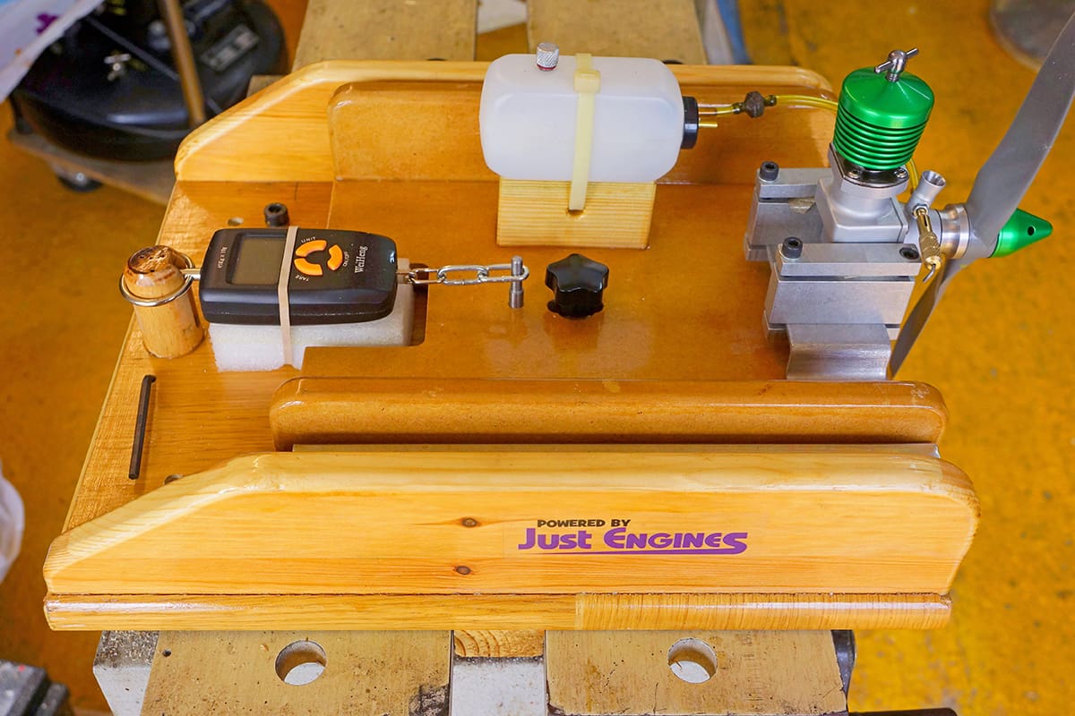
The engine mount was screwed nearly flush with the front edge and on the centre line. A block of wood, to raise the fuel tank and allow fixing of that item, was bonded, and screwed behind and to the right of this.
Reassembling the Deck to the Base then allowed me to see how I needed to fix the digital scale. I wanted it to be easily removed and not to have to chop bits off it to achieve this. The scale has a 1-1/4” diameter ring for hanging it up, at the top. The scale needs to be firmly fixed, so a wooden mandrel was turned to this diameter, to be a sliding fit in the ring. A groove to accommodate the ring fixing was cut in the front face.
The scale was laid in its proposed position to gauge where to drill the base to accommodate this mandrel and a 1-1/4” diameter hole was drilled through for it to be located and bonded. The bottom of the scale had a small length of chain, plus a hook. This was cut off and replaced with a 3” length of 1/4” diameter links to allow it to be attached via a 1/4” diameter stud fixed in the Deck. Position of this was determined by allowing 1/2” of forward movement before the load was put onto the scale. A piece of polythene foam was then cut to pack up the scale to be level with the Deck and to provide some dampening of vibration.
After the whole assembly was stripped and given two coats of PU varnish, this pad was attached for half its length with contact adhesive, to allow a rubber band to be slipped under to hold the gauge down. To ensure only the first runners were used, each second runner was prevented from moving by fixing a screw through a hole at the rear, into the side walls.
TRIAL RUN
The first trial of the completed rig was with a Boll-Aero Major 4.4cc diesel engine, which I had recently made – see Photo 1 at the start of this article. Everything worked to plan, but in trying to take a photo of the scale figures I succeeded in covering my camera in castor oil from the exhaust! So, no photos of that event. At 6500 RPM with an 11”x 6” APC propeller, the static thrust was 21.4 oz. The gauge was also well covered in oil and so, after clean-up, I have now put it in a small polythene bag to protect it.
Now that I was happy that everything worked as I had hoped, I added a column to take an adjustable swivel and lever to operate the throttle control on engines with that feature. (Photo 8)
SAFETY NOTE
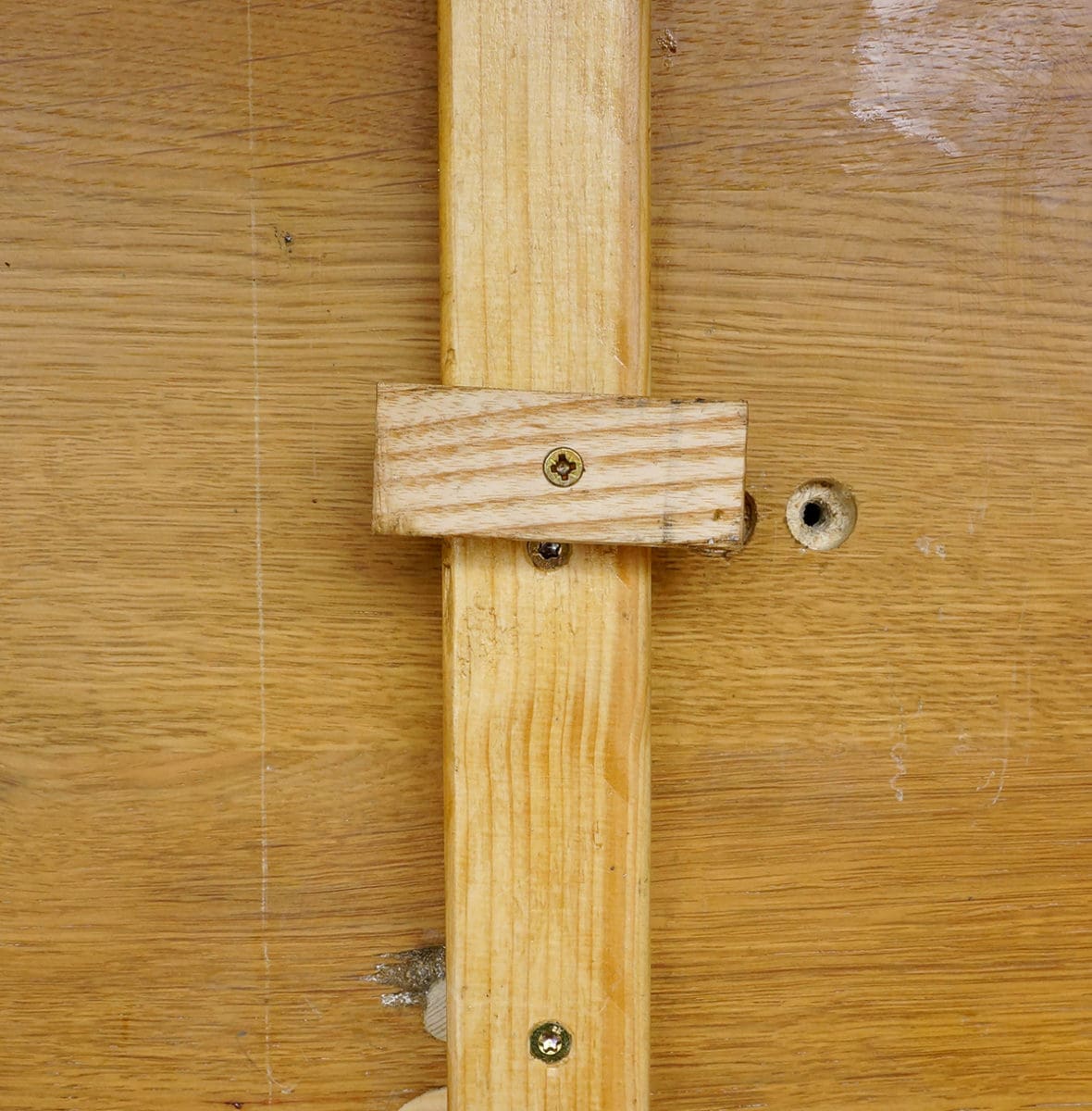
When holding a test rig, such as this, in Workmate type vice jaws, I highly recommend the fitting of an additional cross piece on the batten that it is clamped, to prevent the rig being twisted out by torque when an engine is flat out. (Photo 9)
I had just such an experience and was lucky not to be injured. Fortunately, I was in the recommended position, behind the engine, an 8cc glow, when at 11500 RPM the complete test rig twisted out of the vice and flew across the workshop, landing in a box of wood off-cuts. Other than a damaged propeller, the engine was okay.
Photo 10 shows this glow engine, a Ripmax .48, ready for testing. This was purchased in a very dirty and seized state as ‘Spares or Repair’, but when cleaned up it turned out to be an unused engine.
An interesting aside to this article: I am acquainted with the grandson of William Cody, the first man to fly an aeroplane in England, at Farnborough, Hants, in 1908. He has told me that he has in his possession the large Salter spring balance that Cody used to test the forward thrust of his aeroplane by attaching it to a tree and the tail of his aeroplane while under power.