The Eze-Fan plan can be purchased at MyHobbyStore.com along with the canopy moulding. Back issues (July 2007) containing the plan and this build article are also still available. Click here for extra build pics.
Regular readers will doubtless know that the May and June 2007 issues featured my two-part introduction to the electric ducted fan (EDF) scene. Writing the piece ignited my enthusiasm; a light bulb came on and out came the pencil and paper. EZE-Fan is the result, its a design based on a concept suggested by buddy Steve Sales. Steve had wondered about the possibility of an extremely simple and low-cost EDF design that would literally allow any competent flyer to have a go, whilst providing every chance of success.
THE CONCEPT
From my own point of view, not only would it have to be suitable for hand-launch, thereby eliminating the usual need for catapult or bungee equipment, but said launch would have to be an underarm lob! Its clear that even the mention of needing a catapult or bungee puts about 90% of electric flyers off trying an EDF model, so together we had a point to prove. After a short development period, then, the model presented here appears to have addressed the design brief perfectly.
POWERTRAIN FOR PEANUTS?
You may recall my 30 Tucano published in RCM&E some eight years ago? If you do you might remember that one of the reasons for its popularity was that the motor, controller and flight battery could be purchased for £55. Who would have thought back then, that I’d be presenting another 30″ flat sheet wing design, but this time an EDF model using a brushless motor and ESC unit, with a Li-Po flight battery, all for just £65? What”s more, this package consumes twice the power (i.e. 200 watts) and at 1700mAh offers double the battery capacity. The future is surely bright.
EZE DONE
Article continues below…
Enjoy more RCM&E Magazine reading every month.
Click here to subscribe & save.
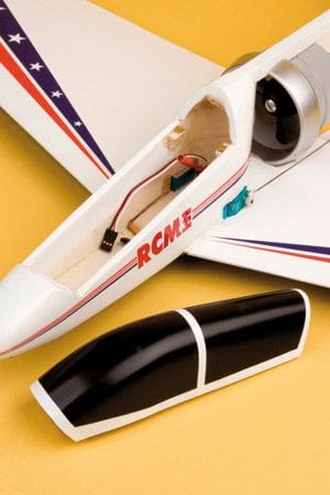
EZE-Fan is a one-piece, all-sheet balsa design with a pod-and-boom like structure. Some say it looks a little like an Alpha Jet while others think there’s a bit of A6 Intruder thrown in, but whatever its influences, it’s sure to please in whatever colour scheme you choose to adopt. At 30″ span it can weigh anything from 16 to 24 ounces (depending on the power set-up), with a surprisingly light wing loading (for an EDF model) which results in very reasonable glide characteristics. Keep it light and it will fly on as little as 100 watts. With 150 watts, however, it’s capable of looping and rolling from level flight, and with 200 watts you have a pocket rocket.
EZE BUILD
With the exception of those specified, it goes without saying that you’ll need to choose the lightest possible balsa grades. Rest assured, if your EZE-Fan comes out heavier than it should, the grades of balsa you used will most likely be the culprit – remember that the strength is in the design not the materials.
Begin, as always, with the wings. All the panels are made from 3/8 (10mm) soft, lightweight balsa sheet. The panels go together with the spacer strips leaving a perfect gap for the 1/8 (3mm) ply dihedral brace. Add the 4mm square spruce to the leading edge as this will not only give good ding resistance but will also provide a physical limit to profile down to. There’s no rear profiling necessary as the ailerons provide for this. Chamfer the rear of the wingtips to match the ailerons, which themselves are simple commercial trailing edge stock.
Don’t forget the small notch in the rear of each wing root which makes the necessary slot for the bottom lug of the fan unit. When the panels have been profiled (as shown on the plan) and the hardwood leading edge nicely rounded, they can be joined with 18mm under each wingtip and the dihedral brace glued in place when set.
 The fan unit can be epoxy glued to the wing using the slot for location, but first you’ll have to razor saw the inlet flange to allow the fan unit body to sit exactly horizontal, i.e. at zero incidence. At the same time, modify the top of the flange and the upper mounting lug to later accept the main fuselage boom.
When everything is ready, glue the fan unit to the wing using epoxy or cyano (roughen up the plastic areas to be glued for better purchase) and allow to thoroughly set whilst constantly checking that zero incidence has been maintained. The ailerons can now be chamfered for downwards movement and temporarily hinged in place, this before profiling the rear of the wingtips to match. Incidentally, dont make the hinges permanent until after covering.
REAR FUSELAGE BOOM
Article continues below…
You’ll notice that the model has the look of a pod and boom type, indeed the reason for this is to give the fan unit efflux the least possible obstruction and provide the maximum available thrust. The large rear fuselage gusset not only stabilises and strengthens the structure, it also provides generous side area to keep the model flying straight. Moreover, it provides somewhere to attach the ESC!
Make the boom from a firm but light piece of straight and strong 3/8 (10mm) square strip and reinforce the upper edge with a straight piece of 3/8 x 1/8 (10mm x 3mm) spruce strip. When this is set, add the fin, along with its triangular supports, and blend into the boom with fine abrasive paper.
When assembled, the tailplane can be glued squarely and centrally underneath the boom, making sure the chamfer in the rear of the boom will allow sufficient up elevator movement. All tail surfaces are made from firm but light 1/8 (3mm) balsa sheet, as is the large rear gusset, which can be cut out and glued centrally along the fuselage pod. Note that there will need to be appropriate cut-outs for the tailplane itself, and for the elevator servo which is mounted beneath (using a very short pushrod for slop-free control) and a 300mm extension lead to connect it to the receiver.
FUSELAGE POD
The fuselage pod is of very conventional construction and uses the softest 1/4 (6mm) balsa sheet you can find. If you cant get anything soft and light enough, substitute it for soft 3/16 (4.5mm) sheet and double the inside faces with 1/16 (1.5mm) sheet.
Perhaps the most important thing to get right is that the cut-outs at the bottom not only match the wing curvature correctly but that in making them, the incidence of the rear boom is not affected. On final assembly the wing, boom (and hence tailplane) and motor thrust line should all be in line with no incidence deviation whatsoever.
Article continues below…
At this point the 3/8 boom support platform can be glued in the correct position, using nicely shaped pieces of scrap 3/8 sheet to provide a neat slot for the boom to slide into.
The moulded plastic canopy, (available for £5 including p&p from the RCM&E Plans Service) finishes the fuselage pod off nicely and is held in place on all the prototypes using small neodymium magnets at the rear in conjunction with a ply tongue at the front.
When the fuselage pod is complete and the underside cut-outs fit the wing profile perfectly, dummy fit the two components using modelling pins and check the rear boom for fit. If there’s any problem aligning the rear boom, you can usually raise the platform slightly using shims of 1/64 or 1/32 ply. You will, of course, have to make a slot in the underside of the boom to correspond with the reduced-height upper mounting lug on the fan unit. Note that when the boom is pushed fully into its slot, the three main units should piece together tightly so you can check everything for alignment.
Underneath, the firm 1/4 (6mm) sheet skid can be glued in place, making sure it mates with the bottom of the rear fuselage gusset – this will be blended in with abrasive paper towards the end of the build sequence, so do remember to leave a small area uncovered.
COVERING
Wrap each major component before final, permanent, assembly. In this respect, Solarfilm is ideal for the EZE-Fan as its both colourful and strong without adding too much weight. You should be able to cover the entire model from a single pack, but do remember to leave the all-important gluing surfaces clear of film. Oh, and by the way, I always use a contrasting colour for the underside so its easy to tell which way up the model is at a distance. The apertures for the aileron servos should be made at this stage and if desired the servos can be attached using the usual screws or, according to preference, permanently glued in position. After covering, the elevator should be hinged to the tailplane and the servo and linkage fitted. Don’t fit the ailerons just yet, well leave that job until last knockings.
 MOTOR ACCESS
Article continues below…
On the first of my prototype models, the motor was built-in, making access impossible after the airframe had been permanently assembled. If you’re happy with this, simply fit the motor and impeller into the fan unit and carry on with the final assembly detailed below. However, the whole idea of EZE-Fan is to encourage you to try different set-ups and configurations, so you may wish to take the following option to make this possible.
On the plan you’ll see a dotted line in the rear fuselage gusset that highlights an optional cut-out just behind the motor. Before final assembly, simply cut this section out with a very sharp knife or scalpel, and put the piece to one side. This allows the motor to be fitted after final assembly, as there will be sufficient access through the intake at the front to reach the motor mounting bolts and impeller centre bolt with a long screwdriver, albeit at a slight angle.
When the motors in position, the cut-out section can be simply tack-glued back in place to hide the ugly gap, and can even be covered in Solarfilm if required. All you need do in the event of a motor change, then, is remove this piece again to allow sufficient space for the motor to be removed.
FINAL ASSEMBLY
Whichever way you decide to fit your motor, final airframe assembly is the same. The most important detail, as stressed above, is to make sure everything is in line when viewed from the side, and that the tailplane is in line with the wings when viewed from the front. Establish that the main structures are a nice tight fit before committing the glue, making any fine adjustments where necessary. When you’re happy, first glue the fuselage pod to the wing using epoxy, then glue the rear structure to the pod and wing unit. Epoxy is probably more suitable than cyano here as it gives you the time to check the alignment before it goes tacky.
The fan unit is now completely sandwiched between the wing and the fuselage boom, this providing an extremely tough assembly which will take a fair amount of punishment. Finally, glue the rear fuselage gusset to the skid, i.e. where they meet behind the fan unit, and then blend the junction of the two parts with abrasive paper. With this, the remaining bare areas can be covered with scraps of Solarfilm.
SET-UPS
Even using the cheap SF grey fan unit, there’s a vast choice of power set-ups that can be used with EZE-Fan, to a maximum of just over the 200-watt mark. My personal favourite is to use the motor designed for the fan unit, which is the SF outrunner in a can. It has the required 2.3mm output shaft and comes in 2500 and 3000 Kv versions; the 3000 is ideal on 3s Li-Pos and the 2500 is awesome on 4s Li-Pos, with neither set-up drawing any more than 17 amps even with a 6 blade impeller.
These motors, as well as the SF fan units and corresponding British made brushless ESCs, are available from M.troniks. This is by no means the cheapest set-up but long-term testing has proved all three items to be totally reliable.
If your objective is to get the EZE-Fan airborne on the lowest possible budget, then Brian Collins of www.brchobbies.co.uk has put together a complete package which comprises the fan unit, motor, ESC and 3s 1700mAh Li-Po flight battery. The package is available with a choice of motor Kvs giving either just over 150 or just over 200 watts depending on how fast or how long you wish to fly.
Whichever way you decide to go, the EZE-Fan provides for simple motor, impeller, ESC and flight battery changes if you later wish to experiment with different set-ups.
CONNECTING UP
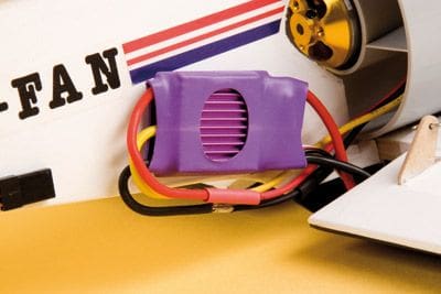
In order to achieve the best cooling, the ESC is simply mounted to the rear fuselage behind the motor using strong double-sided tape with the battery and ESC wires following the skid to a hole in the underside of the wing, where they enter the fuselage pod. The elevator servo requires a fairly long extension lead and this follows the same route, with small lengths of tape securing it to the gusset along the way.
Inside the pod you can connect the ESC, elevator and aileron servos to the micro receiver and route the aerial in a way that avoids the fan unit. Along the underside of one wing is the neatest and most effective route.
Since the elevator linkage will already have been sorted, now is a good time to connect the ailerons, which also use short pushrods that run to a ply horn on the control surface. It’s worth noting here that if the pushrods come too close to the fan unit inlet shroud, you can simply put an equal crank in both to avoid contact. When it comes to mixing the aileron servos you can either use a short Y-lead or, depending on your radio, channels 1 and 6.
The entire forward section of the fuselage pod is home to the flight battery, which can be anything from a 1500mAh 10C 3s pack to a 2200mAh 20C 4s pack, depending on the set-up you’ve chosen. These, incidentally, are the extremes of flight battery I’ve managed to use so far, whilst still maintaining the C of G by careful battery shifting. You’ll see from the plan that the C of G is just forward of the dihedral brace but can be moved by up to 5mm each way depending on taste: that said, don’t forget that this is a fan model with no direct prop-wash over the flying or control surfaces so you will still have to fly it like a jet.
 FINAL CHECKS AND FLYING
For some reason, EDF models always seem to be more prone to glitching than prop-driven aircraft. Quite why is a mystery to me but I do wonder if its because of the high commutation rate that goes with the high motor RPM, and the inevitably close proximity of the electronics.
Check the C of G position and flight battery integrity for the last time; in the excitement to get a new model airborne, these can all too easily be overlooked.
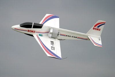
The EZE-Fan has been designed specifically to be launched using an underarm lob, and the best way to do this is by gripping it just behind the canopy and launching with wings level directly into wind at about 30 degrees nose high. If you have any doubts then get someone else to launch it for you and see how easy it is. My 200-watt example, weighing 22 ounces with a 4s 2200mAh Hi-Model Li-Po, can be launched in this manner on a calm day and it simply climbs in the same manner before being pulled vertically up.
Once away the EZE-Fan takes no time to get on its step and will soon be at trimming height. If you’ve built everything straight then little or no trimming will be required. Even if you have inadvertently got the rear boom angle slightly out, the elevator trim will be more than capable of sorting it out.
With nerves settled and the model flying straight you’ll soon get a feel for what EDF is all about. Avoid hanging on the elevator or speed-quashing bank-and-yank manoeuvres. Instead think of it as a jet and fly in big, wide, smooth sweeping turns. Try the stall at height and once reassured that its a non-event, you can become a little more adventurous. Loops, cuban eights and reversals are all perfectly straightforward as long as you keep the airspeed up, and avoid tugging on the elevator, especially on the dive out of a reversal.
The EZE-Fan is pretty viceless and will relieve any fears you may have about jets. Even the glide is pretty decent, better with a three-bladed impeller that is completely stopped, but you can actually use a slow turning EDF unit as an effective brake.
The best approach to landing most EDF models is to fly them onto the ground and cut the throttle as soon as contact is made. I’ve seen many an EDF landing end in tears when the pilot has tried to stretch the glide too far and the model has literally dropped out of the sky. Fortunately, you’ll have no such worries with the predictable EZE-Fan.
 MODS
MODS
Naturally some of you will have fan units other than the cheap 68mm SF grey plastic unit used in the prototype and shown on the plan. So, for those who might have a WeMoTec or AirPower unit that’s physically larger than the one shown, there is no problem – all you have to do is make the fuselage sides proportionally taller, and the rear fuselage gusset similarly deeper. This may sound a little daunting, but as long as you follow the main principle of keeping the thrust line, wing and tail incidences all in the same line (i.e. zero-zero), more or less any fan unit can be grafted in place.
With heavy fan units you can even enlarge the whole model so as to keep the wing loading within sensible limits. What we have found is that if you enlarge the entire aircraft, it is advisable to increase the depth of the fuselage boom by using a piece of 3/8 x 1/2 (10mm x 13mm) strip to manage the extra weight of the bigger tail and generally provide a stronger rear end.
Higher powered examples really shift, as Steve has proved with a 10% larger example using a 70mm AirPower fan unit and a 4s Li-Po set-up, burning 485 watts! This model has an incredible vertical performance and covers the sky like a real jet. Not only that, when it rockets by on a fast pass, the noise from the EDF unit sounds more like a gas turbine than an electric powered model. I’m currently working on a significantly larger twin EDF version of this model, for 2009 so stay tuned.
DATAFILE
Name: EZE-Fan
Model type: EDF sport jet
Designed by: Nigel Hawes
Wingspan: 30″ (760mm)
Fuselage length: 25″ (635mm)
Wing area: 180sq. in.
All-up weight: 16 – 24oz
Wing loading: 19oz / sq. ft.
Control functions: Aileron, elevator, throttle
Rec’d no channels: Three
Rec’d powertrain: 68mm fan unit with
3300 Kv motor and 3s 2100mAh Li-Po


