Based on a pioneering Portuguese aircraft which celebrated its centenary in 2022, Mário Vilaça’s scale biplane is described by Arnaldo Correia.
words >> Arnaldo Correia
photos >> Arnaldo Correia, Mário Vilaça
Enjoy more RCM&E Magazine reading every month.
Click here to subscribe & save.
Anyone reading this grand magazine will surely know that Alcock and Brown were the first to cross the North Atlantic non-stop in 1919 aboard a Vickers Vimy. By the same token it is very unlikely that anyone knows that the first people to cross the South Atlantic by air were two Portuguese aviators. Their flight could hardly be called non-stop, though…
On the 17th June 1922, Cdr Sacadura Cabral (pilot) and RAdm Gago Coutinho (navigator) reached Rio de Janeiro (Brazil) aboard a stock Fairey IIID. This was the third aircraft they used, the previous two having been lost in accidents: a broken float while alighting their special long-range IIID in the open sea by the St. Peter and St. Paul’s Rocks, a small group of islands in the equatorial Atlantic Ocean, and engine trouble with the stock IIID they used next to try to complete the flight.
Above all this voyage showed the new astronomical navigation system they had specifically developed to guide aircraft over a featureless ocean was effective and accurate, as they managed to find those low-lying Rocks, with an area equivalent to just two football fields, in the middle of the ocean after a +900NM leg, using just their specially modified sextant and a new drift corrector.
WHY A FAIREY?
Their voyage over the Atlantic Ocean would take several stages to accomplish, rather than a single one like Alcock and Brown’s, so they needed a seaplane as no landing grounds would be available most of the way. Also, Sacadura Cabral held Rolls-Royce engines in high regard for their quality and reliability, so he chose to use a 350hp Rolls-Royce Eagle VIII. So, using a British engine, a British airframe would be the likely option and the Fairey IIID was chosen. Three aircraft were bought, one a special long-range version and two stock IIIDs, the last ones being initially earmarked for operational use.
WHY THE SOUTH ATLANTIC?
Well, the North Atlantic had already been conquered and in 1922 Brazil, a former Portuguese colony, would commemorate the first centenary of its independence. So, it would be a nice diplomatic gesture to connect both countries by air, as their ancestors had done by sea four centuries before.
That was the official reason. In fact what the aviators actually wanted was to prove that their new navigation system really worked, after their successful Lisbon-Madeira trial flight in 1921.
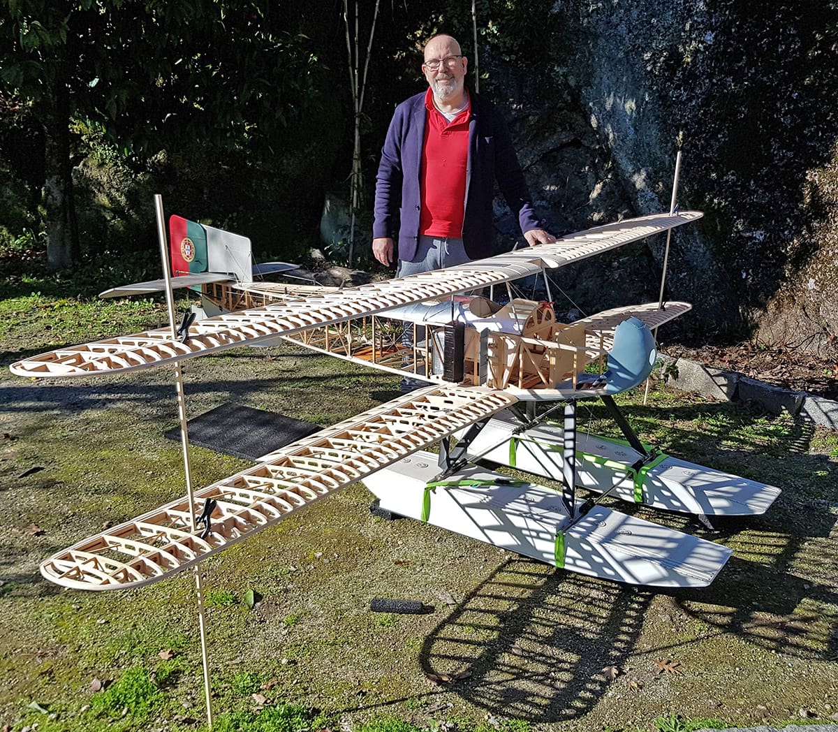
REMEMBER MÁRIO?
Those of you with good memory – or a good RCM&E library! – may remember Mário Vilaça as the builder of some exquisite 1/3 scale WWI German planes, namely a Roland DVIb (August 2019) and a Pfalz DIIIa (Feb 2021).
I remember when, in 2018, while we were both attending a seaplane meeting, after dinner my eyes nearly popped when he produced three beautifully executed and finished relatively large white floats. To an ‘aeronut’ it was not too difficult to identify them as belonging to a Fairey IIID, the only complete one extant in the world having been at our ‘Museu de Marinha’ in Lisbon since 1962. This is the very same aircraft used by the two gentlemen mentioned above to finish their momentous first South Atlantic air crossing.
HOW IT STARTED
Over to Mário:
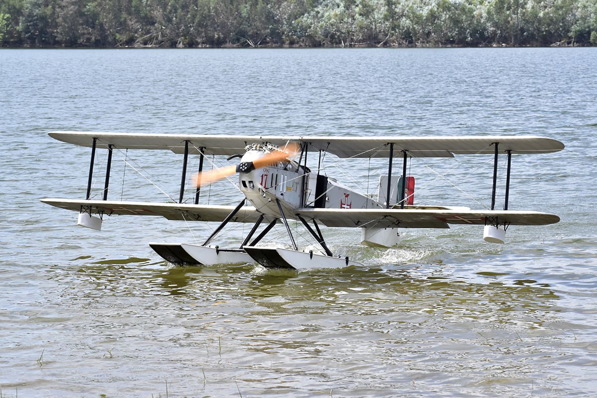
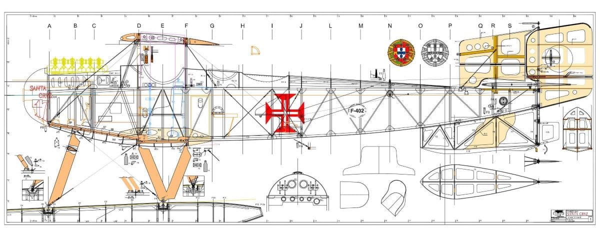
‘In 2017 our common friend Carlos Seabra told me: ‘In five years’ time it will be the first South Atlantic Air Crossing centenary. We both love seaplanes so we must do something to commemorate it. How about a large Fairey IIID?’ For all sorts of reasons, this would be quite a challenge as there isn’t much available info on such an important aircraft. On the other hand, the only existing complete Fairey IIID is in our Naval Museum. The die was cast. We would make a Fairey IIID, more precisely the Fairey 17 ‘Santa Cruz’.
Fairey 17 was the serial number given to it by the Portuguese Navy, according to their then current ID numerical system, while Santa Cruz (the ancient name of Brazil) was added after the crossing had been accomplished.
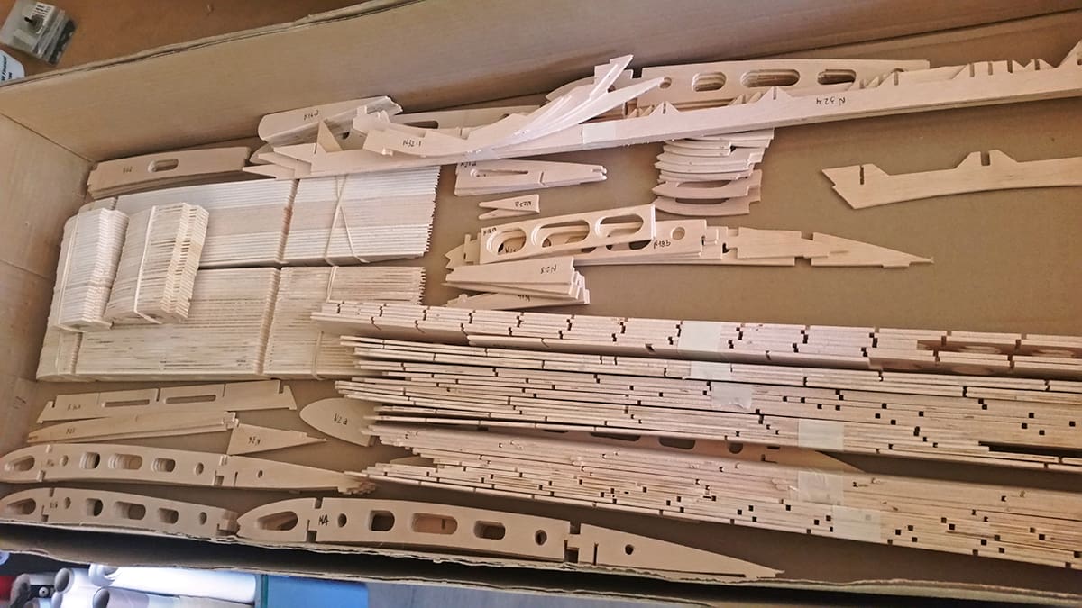
Based on a good set of three-views supplied by Carlos, I would draw the plans using AutoCAD and he would cut the parts by CNC. Although that meant a huge time saving, there was still a lot of work to be done.’
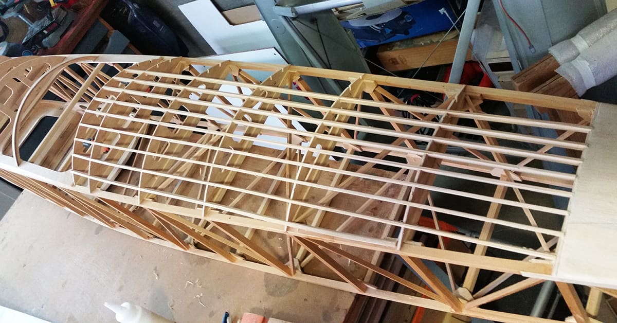
WINGS
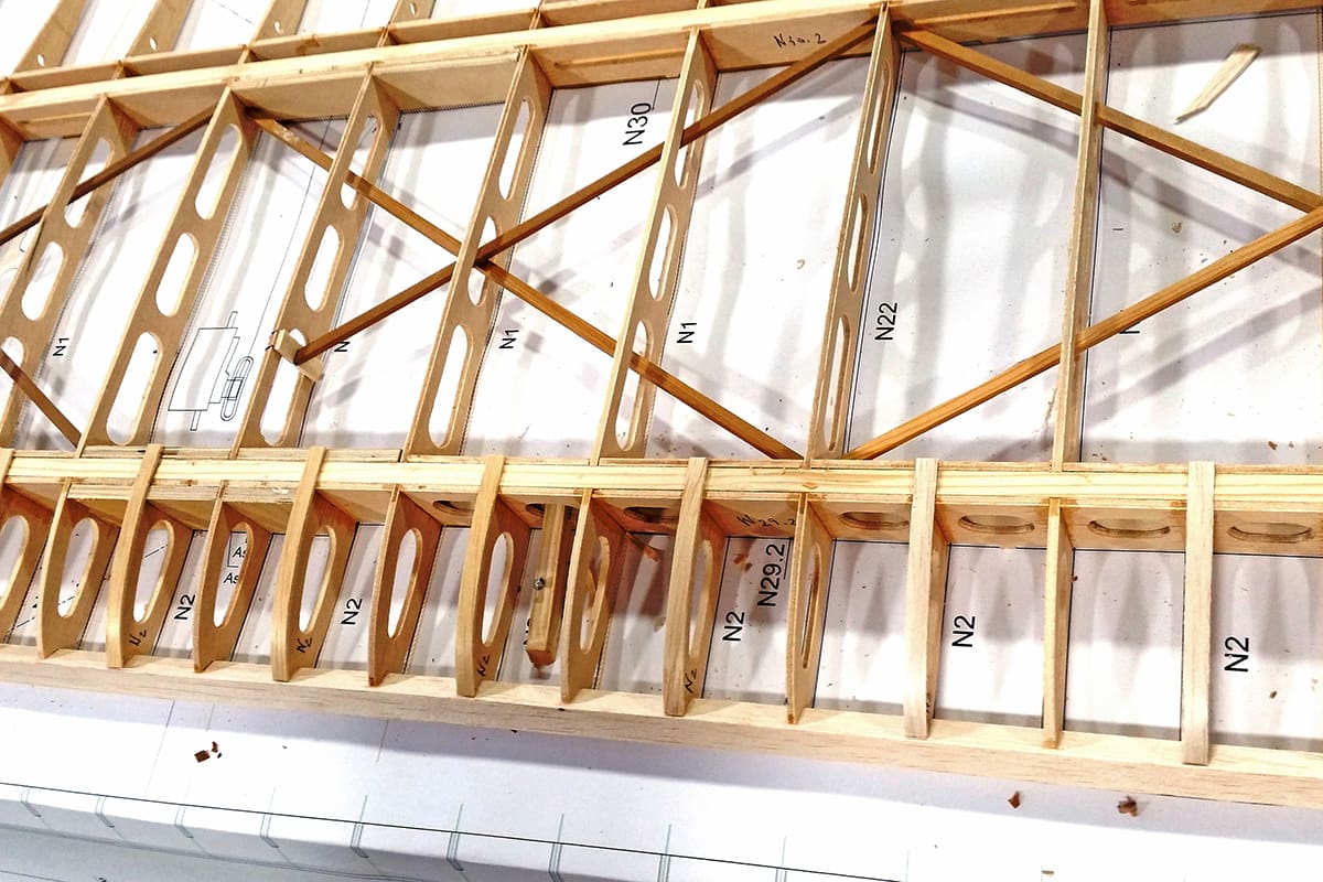
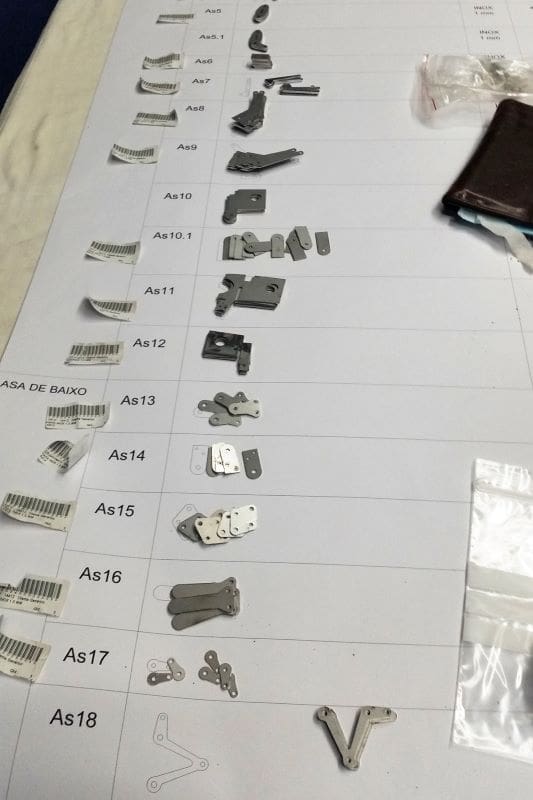
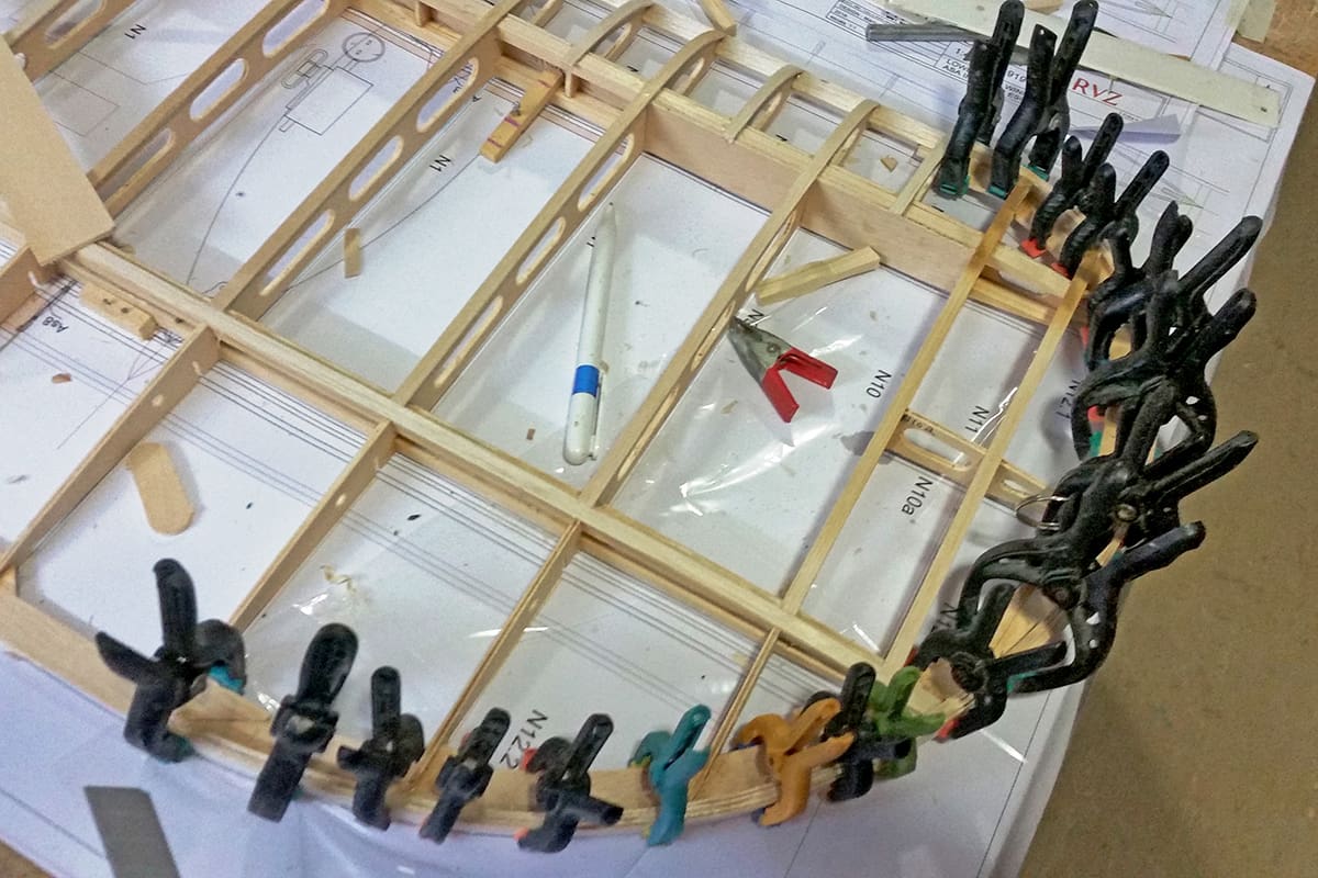
As might be expected, the wing structure is wholly traditional. The wing section chosen was the same that has served Mário well in his 1/3 scale Dawn Patrol models. Main spars are 8 x 8mm fir strips, all flying, and landing stresses are handled by working flying and landing wires. All load bearing fittings were laser cut from 1mm stainless steel, while the non-load bearing ones were cut from 1mm aluminium to save weight.
While the leading edges are balsa, all ribs, riblets, trailing edges and mainspar webs were cut from 3mm 3-ply poplar lite-ply purchased from a local DIY store.
An interesting feature of the wings are the 3 x 5mm pine strips used as stiffeners, which greatly increase their torsional rigidity for a negligible weight penalty. Mário had considered copying the original and use wire tensioners but, in the end, he opted for pine strips as a weight saving measure.
Wings are connected to the fuselage and centre section by 8mm carbon fibre rods riding on aluminium tubes. So, if a flying wire breaks one still has a fighting chance of bringing the model down in one piece.
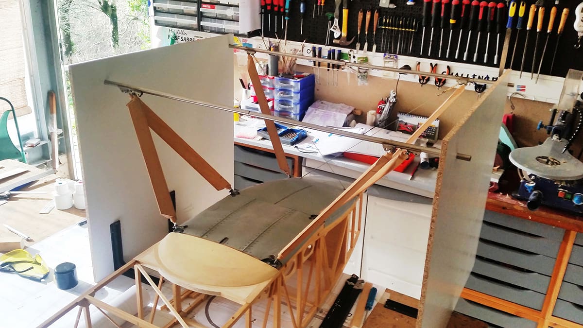
CENTRE SECTION
The cabane winglet follows the wing structure. The four masts are 8mm aluminium tubes, these being braced by wires made from steel fishing trace. On the original the centre section cabane incorporated the fuel header tank that fed the engine by gravity, this in turn being supplied by the main fuel tanks. The pilot’s seat was installed on top of one of these – talk about a hot seat!
The dummy header tank was made from lite-ply ribs covered with balsa, over which 0.3mm lithoplate was glued, with small brass tacks being used to simulate rivets.
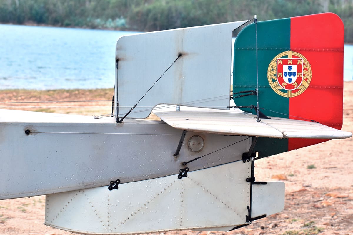
TAIL & WING TIPS
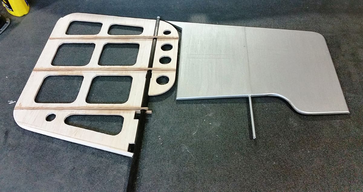
Tail surfaces and wing tips are made using a variation of the ‘Eric Coates method’, first presented in Aeromodeller some fifty years ago, i.e., a central balsa core to which spars, edges, ribs and riblets are then glued. On the Fairey the cores were cut from 3-ply poplar lite-ply, extensively lightened. Mário then applied balsa laminations around the edges, rather than above and below as per the original ‘Coates’ method, forming a ‘T’ that greatly increases the finished surfaces resilience to warping. In this case five strips of 1 x 6mm balsa were used to make the laminations. Given the large radii involved, Mário says the water in the PVA glue is enough to wet the strips for bending. When thoroughly dried, these are rounded out to simulate the metal tube outlines of the prototype.
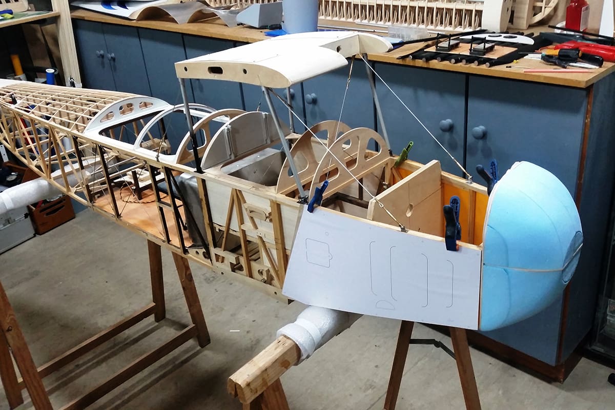
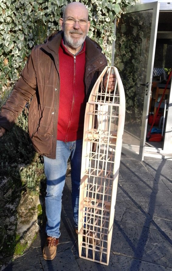
FUSELAGE
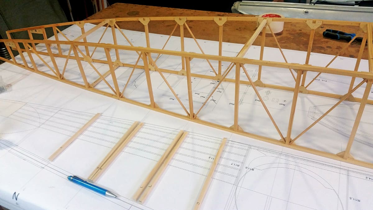
The fuselage is made from 8 x 8mm fir longerons and spacers for the main structure, just like an over-grown Keil Kraft kit, reinforced with CNC-cut 3mm poplar lite-ply gussets. To increase torsional rigidity 5 x 3mm fir strips were glued diagonally to the gussets. Being only 5mm deep, they do not show up under the fuselage covering.
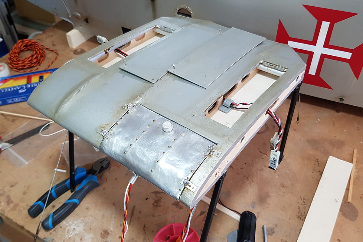
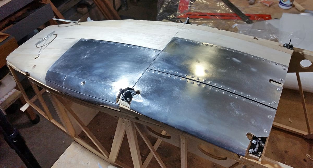
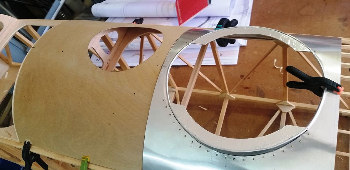
Formers were cut from the same poplar lite-ply used on the wings, the exception being the firewall, which was made from two crossed laminations of 5mm Finnish ply, as the 130cc Roto engine bolts onto it. 5 x 3mm fir longerons were used on the rear turtle deck, while the turtle deck front panels were made from 0.3mm lithoplate glued over 0.4mm plywood panels to stiffen them.
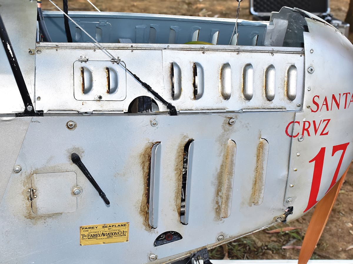
The cowling flat side panels were cut from 1mm aluminium sheet, with single-bend cowling louvres being cut directly on it, while the rounded ones were 3D printed and glued to their respective panels.
The fuselage nose tip is the only large glass fibre moulding, made over a blue foam male plug by the lost foam method. The front flap door is an interesting full-size detail; Mário believes it was there to give easy access to the two front carburettors, the original V-12 Rolls-Royce engine having four carburettors, two at the front and another two at the rear.
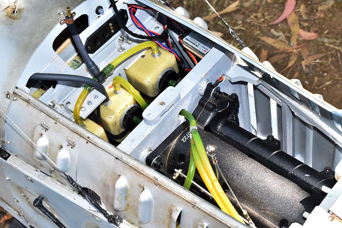
One of the problems Mário faced was where to put the model’s fuel tank. For practical reasons it had to be in front of the dummy instrument panel but that meant the length available would be short and that could jeopardise consistent fuel feed. Taking advantage of the wide fuselage Mário copied the system often used in jets, i.e., two auxiliary fuel tanks seated abreast a header tank and feeding it, with the header feeding the engine.
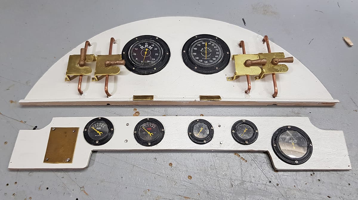
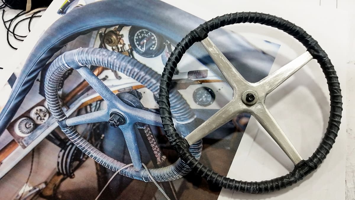
Since photographing the original instruments at 90 degrees was impossible due to the large control wheel being in the way, Mário drew these using Corel and printed them with a laser printer. Bezels were 3D-printed rather than turned from metal, to save weight.
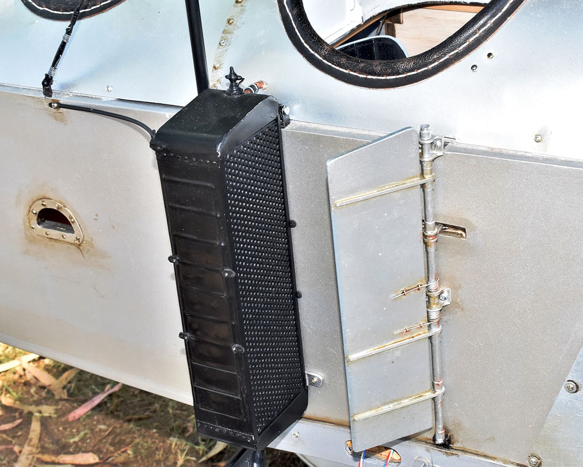
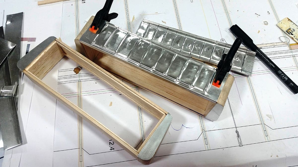
RADIATORS & VANES
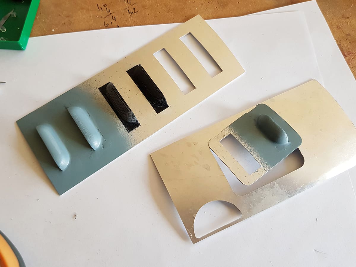
The radiators’ honeycomb cores were 3D printed, while header tanks and frames were made from balsa, covered with 0.3mm lithoplate. The side panels were also from lithoplate, carefully embossed by gently forming the lines over a piano wire piece half-sunken into and glued to a hardwood block. Mário says the most demanding part was to replicate the existing dents as closely as possible!
The side vanes, used to control the air flow to the radiators and hence the cooling water temperature, were cut from lite ply, with hinges/stiffeners cut from 1mm aluminium and hinged on an aluminium tube.
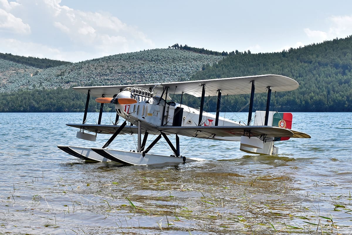
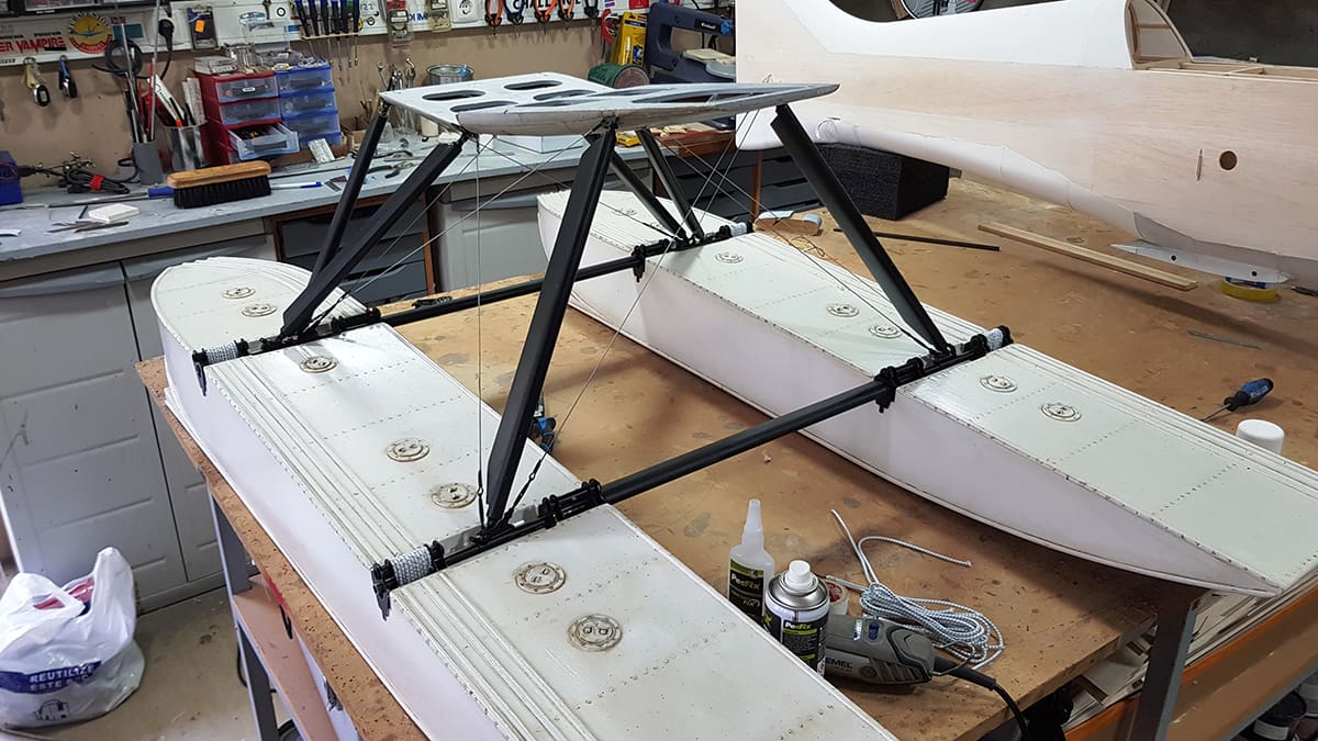
FLOATS
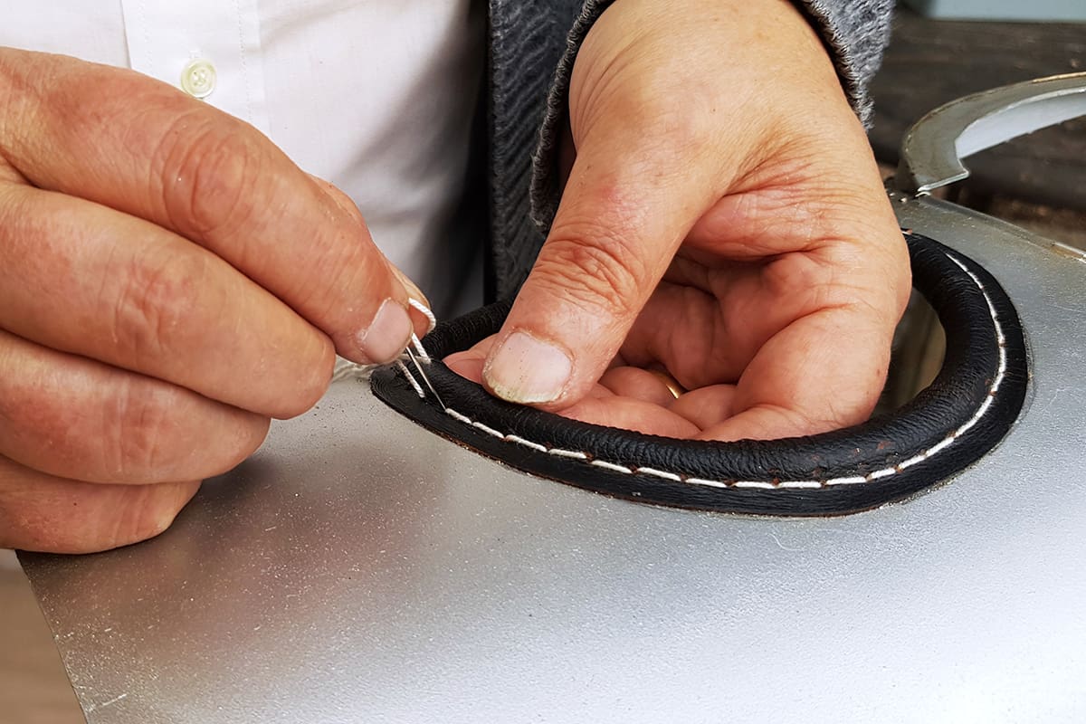
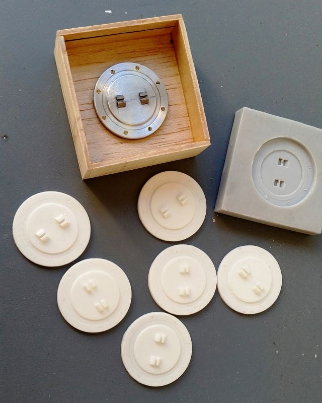
The main floats were built with 3mm poplar lite-ply for the sides and bottom, balsa being used for the top as a weight-saving measure. These early floats had flat bottoms, so their cross sections are rectangular, the V-shape coming into use only some years later.
Before details such as the anti-slip strips and inspection covers were added the main floats were covered with 25g/m2 glass fibre cloth applied using water-based acrylic resin. The main float legs were carved from Scandinavian redwood, a beautiful close-grained strong wood, and the embedded end fittings were laser cut from 1.5mm stainless steel. The suspension is functional and uses bungee cord supplied by Mick Reeves.
Tail and wing floats have a lite ply inner structure, the tail float being planked with balsa before it too was covered in 25g/m2 glass fibre cloth and water-based acrylic resin, like the main floats. The wing tip floats inner structure is similar, but these were covered in Oratex, to emulate the canvas covered full-size ones.
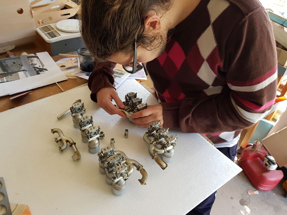
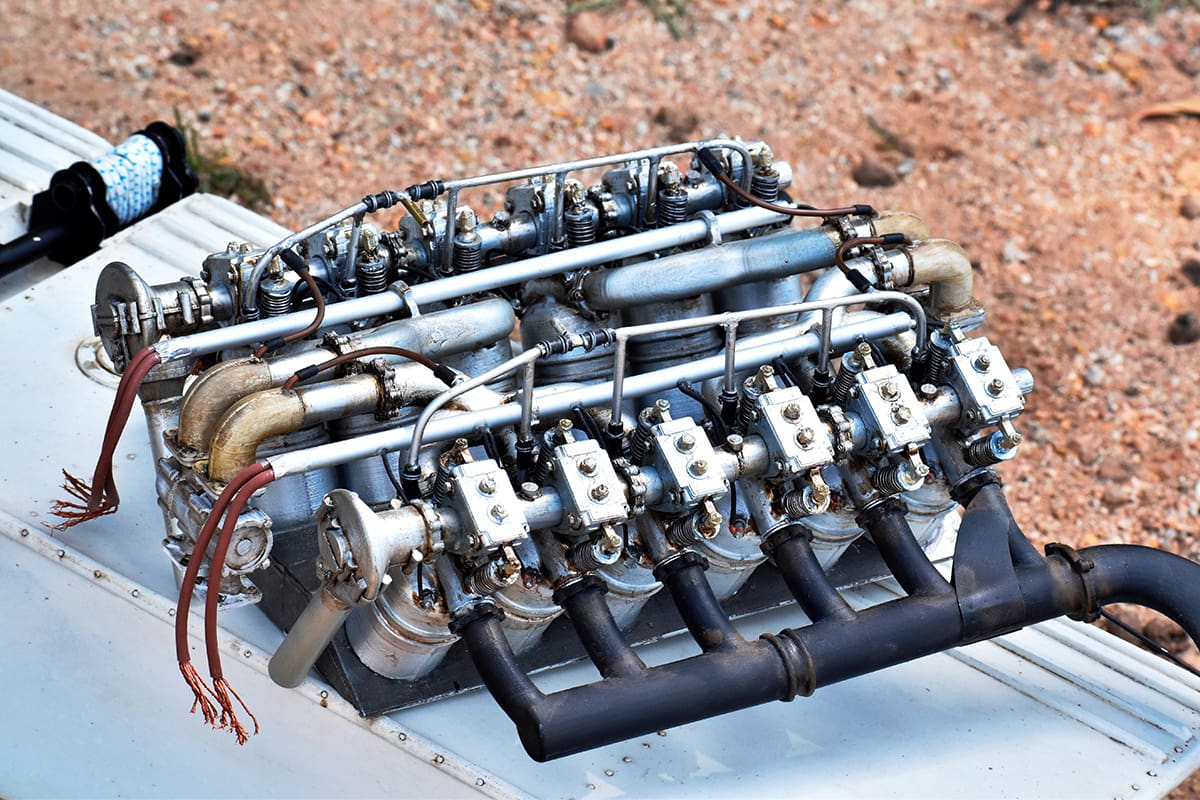
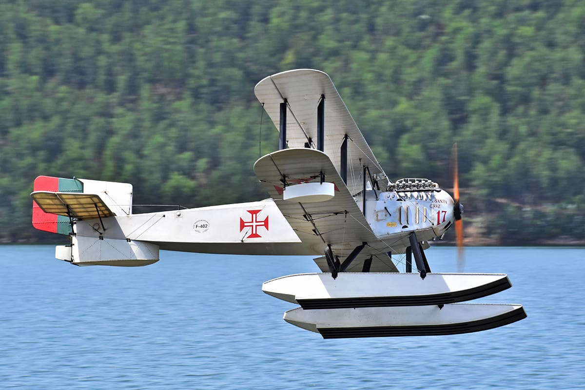
DUMMY ENGINE
This is a work of art. The prototype was powered by a Rolls Royce Eagle VIII and the dummy engine faithfully reproduces the visible parts of the original. Young Anthony modelled it in CAD so Mário could then 3D print the main components, such as cylinders, camshaft covers, manifolds and exhausts, while aluminium, brass, copper and PVC tubes were used to simulate both the piping and visible shafts. Although hardly visible, the four carburettors, two at the front and two at the back, are there too.
COVERING
The model was covered in Silver Oratex overall, rib tapes being applied where needed, before being given a single coat of water-based aluminium automotive acrylic paint.
Mário feels that the Silver Oratex gives a nice base for the final aluminium colour, which allowed him to use just a single coat of paint, while the paint coat allows for better colour control and has the advantage of accepting weathering much better than plain Oratex.
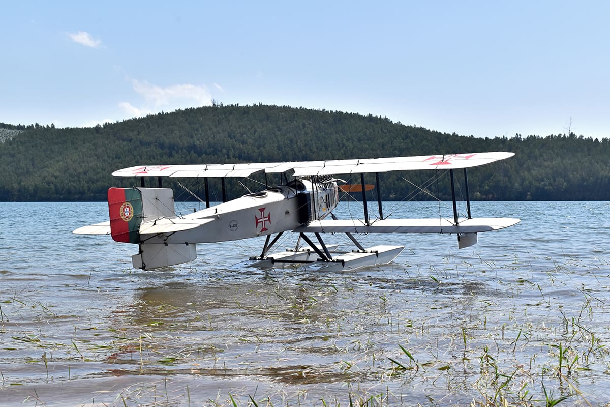
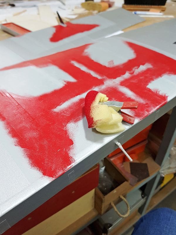
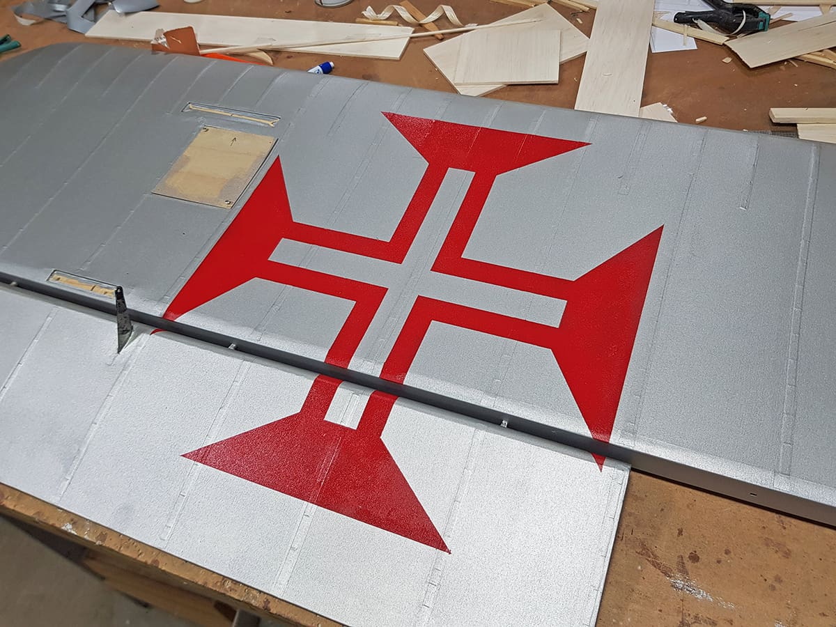
MARKINGS
These were mostly painted using self-adhesive translucent frosted vinyl masks. The way Mário applies the paint is quite interesting. Rather than using an airbrush or paint brush, he uses a small sponge that is lightly dipped in the paint, which is then ‘brushed’ over a sheet of paper until it leaves almost no paint marks. The sponge is then stippled over the area to be painted; this process is repeated several times until the necessary depth of colour is obtained. Mário says that if done carefully there is no risk of paint creeping under the masks, as the paint transferred to the surface with each stroke is so small.
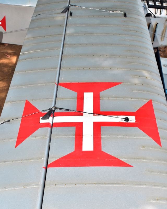
With the national insignias being only straight lines, masks were hand-cut using a scalpel and a straight edge; nose letter masks were plotter-cut though, as they are more intricate.
The only markings not painted were the ‘F402’ construction numbers on the fuselage, these being custom made dry transfers by Flightline Graphics. As you may remember, one must rub them in place with a blunt instrument, so a plywood scrap was placed under the covering for support whilst rubbing them down.
WEATHERING
As Mário likes to point out, weathering helps bringing details up, and gives ‘depth’ to the model. In the present case, the prototype being modelled was quite new, so weathering was light and only walnut wood stain was used, there being no need to simulate rust or soot. Wood stains take their own time to dry out and Mário takes advantage of this whilst applying weathering – the sooner you clean the stain, the lighter the mark left will be. As always when talking about weathering, less is more.
After all the markings and weathering had been applied, the whole model received a couple of coats of water-based matt acrylic varnish to protect them and give the model an ever so slightly satin finish.