The Fizza plan can be purchased at www.myhobbystore.com
As electric motors get more powerful and efficient, and battery capacities go up and their weight comes down, its very easy to get carried along by the mania for the latest and greatest gear. Before you know it, you find that you've lashed out far more money than you intended on some specialised piece of equipment for a complex model – last years twin-400BL Tornado being a case in point! The idea behind this column, though, is to promote low-cost, entry-level electric flight. So this year, instead of my usual semi-scale offering Ive decided to get back to basics and bring you a model that'll put some fun into your flying without costing a fortune.
ANSWERING THE CRITICS
While the Fizza is similar to previous Hawes offerings in so far as its minimalist, functional and robust, I've tried to make this design appeal to my most critical audience – those of you who've not been tempted to build my previous models. I realise that some of you don't fancy flat sheet wings, either because you don't want to profile them, or aren't convinced of the outstanding qualities and benefits. Others have doubts about my nipped tube link aileron set-up – although I have to say that it works perfectly well for the thousands that use it!
With the Fizza, then, I hope that I've come up with a way of making the flat sheet wing attractive to everyone, and introduced an alternative method of aileron operation without compromising the design. Talking of compromise, I should emphasise that your choice of balsa will make a big difference to the final performance of a model of this size. The Fizza's strength lies in its design not in the materials, so you can use the softest, lightest balsa you can find, and the minimum amount of glue. Every ounce you save increases the Fizza's performance and your capacity for fun.
Article continues below…
Enjoy more RCM&E Magazine reading every month.
Click here to subscribe & save.
A WING IN 20 MINUTES
Well, excluding the glue drying times, that is. Even so, youll find that this wing is very quick to make, especially for those whove had a go before.
To make it, all you need is a length of 1/8 hard dowel (which makes for very tough leading edges), two sheets of 1/4 x 3 balsa (one of which should be firmer than the other), and a length of appropriate size trailing edge stock. Oh, and dont ignore the 6 x 1/16 ply spar and spacing strips. They're included to guard against wing failure by replacing the strength lost as a result of the aileron servo cut-out.
After cutting the main wing panels and butt jointing them using the spar and spacers, glue two pieces of dowel along the lower half of each leading edge, leaving a 2 (50mm) gap between the dowels inner ends. This join is best carried out using medium cyano and should be made on a level surface to ensure that the wing is absolutely flat.
Next, add the tips, noting that the they extend 1/8 forward of the wing panel so that theyre level with the leading edge of the dowel. Use five-minute epoxy for this – a cyano joint may be too brittle to withstand profiling later on.
When everything has set, mark out the extent of the wing profiling with a line drawn 45mm behind, and parallel to, the leading edge. Then sand the wing so that it tapers down to the width of the dowel, being careful not to sand any flat spots into the rounded edge of the dowel. Once you're happy with the leading edge profile, cut a pair of ailerons from your trailing edge stock such that there's a 21/4 (55mm) gap between them in the centre, and a 1mm clearance at each tip. Don't hinge them permanently yet, though if you're using Mylar or flocked paper hinges you can loose fit them.
The taper of the ailerons completes the aerofoil section of the wing, so no further profiling is necessary. All that remains to finish is to taper the rear of each tip to match the ailerons.
Article continues below…
AILERON LINKAGE
To control the ailerons, the Fizza uses torque rods made from 16swg piano wire that run in guides made from short lengths of orange inner poached from a lightweight SLEC snake. The guides are simply epoxy glued to the back of the wing panel and holes are made in the ailerons to correspond with the torque rods.
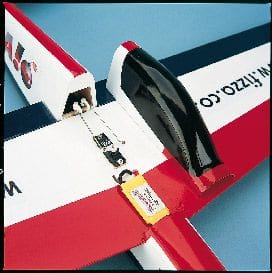
The rods themselves can either be operated by nipped tube links from the servo pushrods, or you can try my new alternative method. This involves sliding a small piece of silicone tubing down the vertical part of the torque rod to form a seal, placing a commercial plastic aileron horn where required, and filling the hole in the top of the horn with epoxy. Although the horns initially feel very loose on the piano wire, the epoxy keeps them firmly in place and they'll never fall off. Having said all that, the access to the torque rods afforded by this model means that you can solder eyelets or ball links to them if you want a really cast iron set-up.
Article continues below…
THE FIZZ-ALAGE
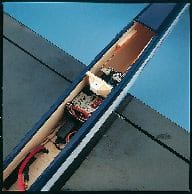
The fuselage is simplicity itself and has been designed with several issues in mind. For a start, making it a mid-wing model not only means that its cavernous battery bay will accept all manner of flight batteries, but also makes for a model that's extremely easy to hand-launch, as you can grip it firmly around its centre of gravity.
The fuselage is also strong, thanks to the doublers along the whole front half, and in the event of a prang, the position of the all too vulnerable ESC on the top side of the wing may help minimise the effect of any loose-cannoning by the battery!
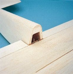
Fuselage construction starts by fitting the doublers to the fuselage sides, noting that the sides need to be handed; use medium to soft sheet for all these parts. Then, keeping the fuselage sides parallel, join them to the vertical edges of the main former F1 which locates with the rear edges of the doublers. Do not, however, apply glue to the angled faces yet.
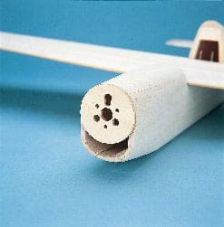
Next, loose fit the wing onto its seat and mark where the flat-edged triangle pieces need to go to support the front upper deck, and then glue these braces into place. The motor mounting disc can then be glued in position using epoxy, making sure that its upper edge protrudes 1/8 above the triangular stock.
Obviously, you'll need to use the correct disc for the motor you're going to fit. Fellside Precision Cutting can supply CNC-machined ply discs for more or less any motor thats suitable for this model, including the recommended Typhoon 6 and 15, Mega 16/15/4 or 5, Tornado 2815, 2000 or 2900, Speed 400 or 480. Make sure, though, that you glue the disc in place in such a way that the motors wiring can run along the lower face of the upper deck rather than dangling into the battery bay.
Once the epoxy has set, glue the front upper deck in place and, turning the fuselage upside-down, add the two 30mm lengths of triangular stock to the lower corners, and finally fit the front underside sheeting. This sheeting can be as firm as you like: its a lob-and-land model, after all, so this bit will take the brunt of your landings.
THE BLUNT END
With the front end of the model ready for shaping, turn your attention to the rear end. Here, former F2 needs to be tapered so as to meet squarely with the sides of the fuselage when theyre pulled together. When you're satisfied that each fuselage side will have an equal curvature and that the tail platform is level with the wing seat, glue the sides to the rear former. When set, add the rear lower sheeting to give the whole structure some rigidity.
Article continues below…
At this stage, you can glue the fuselage sides to F1. If youve used medium to soft grade balsa for the sides, you should have no problem bending them to shape. If your sheet stock is a too rigid, however, dampening its outer faces will allow you to bend it to shape without it cracking.
When everything is thoroughly set, run a sanding block along the rear fuselage upper edges to give a good, flat contact surface for the rear upper deck. Then, holding the fuselage sides carefully so as to give a gradual taper from the main former to the rear end, glue the rear upper deck in place. This is best done by running thin cyano along the joint and allowing it to soak in.
Next, cut the large access hatch from light but firm 3/16 sheet, and trim it to give a perfect fit between the front and rear lower sheeting. I'll leave you to use your preferred method for retaining the hatch; I simply glue a 1/16 ply tongue to the front (which is a tight fit between the doublers) and use a single screw running into a retaining block glued to F1.
SHAPING THE FUSELAGE
Starting from the front, the upper deck should be shaped so that it tapers gradually from its full 3/8 (10mm) thickness at the canopy end to 1/8 (3mm) where it meets the motor mounting disc. The two pieces of 30mm triangular stock in the bottom corners can be blended into the curvature of the underside. When you're happy with the overall shape, use a round file to open out the air intake below the motor disc.
The rear upper deck also needs to be shaped so that it curves smoothly along its entire length. It's important, however, not to remove too much material towards the rear; it must remain 3/8 (10mm) thick along its length.
With the access hatch in place, blend the three underside parts with each other, and with the fuselage sides so that you end up with a nicely rounded body that should be both light and strong.
MAKING THE TAIL
Test fit the wing to establish that its level with the main panel of the tailplane, and make careful use of a sanding block to make any final adjustments. When you're satisfied, mark out the tailplane's final position by measuring between its front corners and the rear corners of the corresponding wing tip, and then glue it into place.
The tailplane's leading edge panels are made from slightly firmer balsa, and their inner faces are trimmed so as to meet the fuselage at the correct angle. Fit the tail surface tips using epoxy, and when everything's dry round off all the forward-facing edges before notching and joining the elevators with a piece of 1/8 dowel. Chamfer the elevators leading edge to allow correct movement, and check that there's a 1mm clearance between the elevator and the tips. Like the ailerons, the elevator shouldn't be permanently hinged until after covering, but again, if you're using Mylar or flocked paper hinges, you can loose fit it now.
When you glue the fin into place, take time to ensure that it is both vertical and aligned with the fuselage. Having rushed this job on other models and ended up with 88° fins that have resulted in hands-free circuits, I now pin the fin in place while I check its position, and only when I'm perfectly happy do I commit with the thin cyano.
The leading edge of the rudder also needs to be chamfered, and relieved so that it clears the elevator joining dowel. Don't forget to check that both control surfaces give full and free movement.
Finally, before gluing the rear tail blocks into place, cut and sand them so that they extend the taper of the fuselage deck all the way to the rear of the fin. This not only finishes the lines of the model, but also gives the fin some valuable support.
FITTING OUT
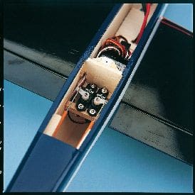
With the wing removed, you can now cover the fuselage and tail unit, and fit most of the radio gear. The elevator and rudder servos simply sit on rails behind F1, though the location of the flight battery depends on the motor you're using. With very light motors such as the HET Typhoon Micro 6, you'll need to position the flight battery as far forward as possible, especially if you're using Li-Po cells. With heavier motors (the Typhoon 15, for example, or 400BL motors such as the Tornado 2815), you wont need to worry about forward-ballast so much.
Your control linkages can be made using either snake or pushrod set-ups. I did a bit of both by having 18swg piano wire pushrods (with a z-bend at the servo end) running inside outer snake tubes to keep them honest. The Rx, meanwhile, will fit neatly into the rear of the battery compartment providing that your aileron servo isn't too deep. My GWS Naromax servo left plenty of room for a GWS eight-channel Rx and all the wiring.
As I mentioned earlier, the motor is fitted with its wiring running along the underside of the upper deck, and you'll now find that the flat-edged triangular stock used to support the upper deck provides a perfect routing. Adjust the lengths of the wires so that the speed controller can sit on the leading edge panel of the wing when its inserted.
You can cover the wing either before or after its slotted into place, though if you do it before you must ensure that the fuselage contact surface is left bare. Before you glue the wing into place make a final check that it'll be level with the tail, that the distance from wing corner to tail tip on either side is equal, and that there's sufficient root clearance for the ailerons.
NUTS, BOLTS & OPTIONS
Drill two holes through the wing and into the battery bay for the battery wires. To fit the aileron servo, you can either screw it to two small squares of ply, or simply drill the balsa and harden the screw-holes with thin cyano; either way, the servo wire should exit right beside the Rx. Then connect up the torque rods using your preferred linkage method, and ensure that they don't foul where they run through F1.
Because the Fizza isn't particularly large, I've designed it as a one-piece model. It would be a doddle, however, to make the wing removable by using a nylon wing bolt front and rear, running into captive nuts held by cross members. This has been tried, and while it does infringe on the battery bay, it doesn't cause any problems if youre using slim cells such as KAN 1050, GP1100 or Li-Pos.
Some of you may want to fit an intermediate former between the battery and the motor to avoid the two coming into contact in the event of a hard arrival. My own feelings, however, are that this would restrict cooling airflow in normal circumstances, and do little to restrain the flight battery in abnormal circumstances! Better by far to make sure your battery's well secured in the first place. Talking of cooling, make some air exit holes where you feel they're needed, the obvious place being towards the rear of the battery access hatch.
CANOPY
The Fizza canopy is available from Vortex Vac-form for £4.00 (inc. UK p&p). Although it has been designed to fit perfectly, there's no reason why you couldn't line the inner edges of the aperture with soft 1/4 square strip so that the edges of the moulding wont mark the wing. To attach the canopy, you can use a small screw front and back running into the upper decking, double-sided tape, or just glue it on if you're not worried about having access to the aileron servo or ESC.
BALSA FORMOSA?
Once all the movements have been set up and you've ensured that the flight battery's secure and positioned to give the correct C of G, the model is ready for its maiden flight.
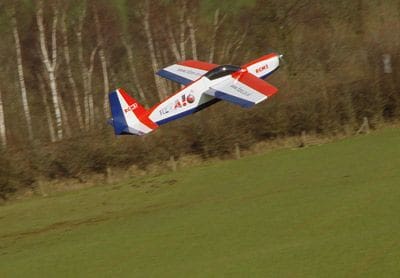
While the mid-wing format makes the Fizza ridiculously easy to launch, its a good idea to get someone reliable to do it for the first flight so that your thumbs are on the sticks from the word go. That said, none of the Fizza's built so far have required any significant trimming – another major benefit of the models flat sheet wings and zero-zero incidence.
Depending on your motor set-up, the performance of your Fizza will be anything from mild-mannered to manic. Using the Typhoon 6/23-turn on a 2s Konion (or seven 650 AAA cells), the model weighs only 14oz, and even drawing just 5A with an APC E 8 x 6 prop will still loop and roll without fuss. Step up to an 81/2 x 8 JP Expert prop, and you'll have a really good sport set-up on either seven or eight cells, or 2S Li-Po.
However, if you go for 10 x 1050 NiMHs and a Typhoon 15/13-wind on a 9 x 6 APC E, the Fizza becomes a rocket ship – even at 14A! The weight does go up a little to 20oz, but this only serves to give the model extra momentum which, allied to a huge increase in power, provides more authority in the sky. Even at the heaviest test weight of 24oz, the models long flat glide was still a joy.
Whatever spec you choose, though, you'll have a model that flies as straight as a die, has no vices, and is virtually tip-stall proof. Its so responsive that it'll give you three rolls per second. With sufficient rudder movement you can really tie it up in knots with flick and spin manoeuvres, but all it takes to recover is to centre the sticks. Those who have already flown one of the prototypes haven't wanted to give the transmitter back, and several testers have described the Fizza as a balsa Formosa. Given that the Formosa was my favourite model of 2004, and probably inspired the Fizz in some ways, I'll take that as a compliment.
AND FINALLY…
So there it is. I hope that you decide to build a Fizza. Its not only quick to build, but because it accepts a wide variety of power sources, its a way to get lots of fun from gear that you probably already own. We hope to have good few Fizzas flying at Sandown this year, which should make for some fine entertainment.
CONTACTS
Vortex Vac-form (for the canopy)
Tel. 01162 207080
DATAFILE
Name: Fizza
Model type: Sport / aerobatic
Designer: Nigel Hawes
Wingspan: 32''
All-up weight: 14oz
Rec'd powertrain: 8 x 6'' APC E prop, Typhoon 6/23-turn motor, 2s Konion or seven 650 AAA cells
Control functions: Aileron, elevator, rudder, throttle
Canopy: from Vortex Vac-form
BUILDERS BACK-UP
To make the Fizza even easier to build, Ive created a fully illustrated, step-by-step guide on a website at www.fizza.co.uk
DEDICATED FORUM SECTION
Click here to visit the Nigel Hawes plan builders forum section and
here to leave your own review of the Fizza.


