
Tony Nijhuis describes the 33-inch version of his Yellowjack RAF trainer for 70mm Electric Ducted Fan units
words >> Tony Nijhuis
words and photos >> Tony Nijhuis, David Ashby
Those of you who have built and flown the 50mm EDF version of the Folland Gnat we launched last year will hopefully agree it was a cracking little model. I always thought a 70mm EDF version could be on the cards if a 4S version became available and was cheap enough, and light and powerful. Sure enough both FMS and Powerfun have now produced a lovely little 4S unit that really suits a scaled up version of the Gnat and, in fact, the whole of the 50mm EDF range! So, let’s start with the Gnat, as it proved to be the most popular model in the 50mm series. But just to whet your appetite, after the Gnat the two remaining models we have lined up for you are the Hawker Hunter and the Jet Provost.
Enjoy more RCM&E Magazine reading every month.
Click here to subscribe & save.
Yellowjack Gnat

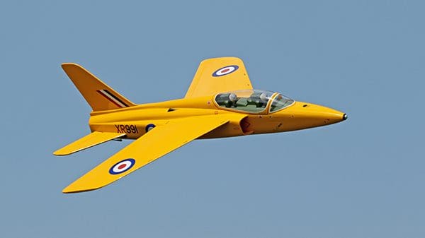
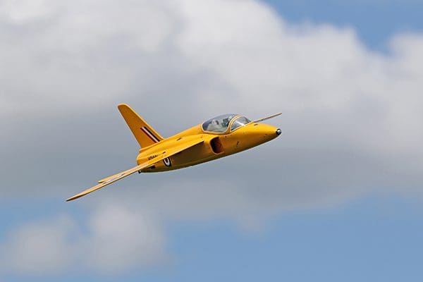
I have always been a long-time fan of the Gnat and when I saw the full-size Yellowjacks Gnat at North Weald aerodrome recently I thought it was a great colour scheme for such a lovely aircraft – I was in love!
One of the key elements I really wanted to achieve on these new ‘Midi’ sizes of model was to keep the wing loading down to less than 25 oz./sq.ft. and under 3 lbs AUW.
By scaling up the smaller 50mm EDF Gnat by 140% you should be able to just drop a 70mm fan into the model. In theory this would be the simplest thing to do. However, enlarging a model design does command a weight penalty, which appears to be exponential. There is a simple rule of thumb that scaling up a model by 200% (or double) will result in the larger model being 4 to 5 times heavier! Therefore, scaling the little Gnat to 130% and not 140% will save around 8oz and keep the AUW to under 3 lbs. Well, that’s the theory anyway…
The Gnat, at 33” span, did come out at 2 lbs 14 oz, so not too bad. The key to this weight and size is that the model can still be hand launched, either by the pilot or a trusted helper.
This new ‘Midi’ jet has been tested using the 4S FMS 70mm fan unit, which gives around 2.75 lbs or 1200 g of thrust. Also available is the 4S Powerfun unit, available from 4-Max.co.uk, and these units will give another 200g or so of thrust over the FMS version and are considerably cheaper too.
Some of you may be tempted to use a 6S version of either fan but there really isn’t a benefit to this unless you already have a stash of 6S 3200mah LiPo packs kicking around.
To assist the builder, I have once again made available a canopy and, to complete the package, a CNC/wood pack is also available for those who wish to make the building process a little easier and quicker. These parts will ONLY be available through Tony Nijhuis Designs Ltd (TND). The plan itself will only be available in this edition of the magazine, with future copies only being available through TND Ltd. At the time of writing this article we are experiencing yet another balsa wood shortage so please check our website for availability of the CNC/wood parts.
Other points to note
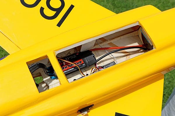
The battery was a 4S 4000mah 30 – 60C LiPo and the servos were cheap and cheerful 10g, 2 kg/cm torque micro servos. For the ESC buy a cheaper 60 – 80A 4S unit as it will be lighter and hopefully have none of those unnecessary programming features. You want a simple switch on and go.
Lastly, and possibly the most important, a photographic build log is available as a free download to print out from www.tonynijhuisdesigns.co.uk.
These photos will be invaluable, and I would suggest downloading them so you can familiarise yourself with the build before you start.
Wings
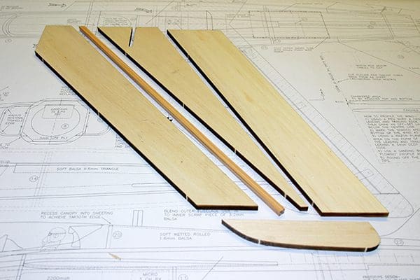
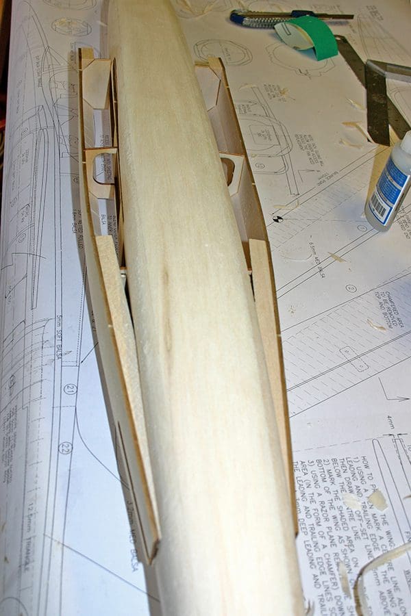
The wing parts are made from 8mm (5/16”) medium density balsa sheet and each wing panel is made of four parts, plus an 8mm square spruce spar. Weigh the individual parts and interchange them in order to achieve an equal balanced wing. Now glue the wing parts together to form left and right-hand wing panels.
Where indicated on the plan highlight the location of the area of balsa to be profiled. A guide to shaping the wing is shown on the plan. With the wing panels flat on the building board use a razor plane to profile the wing panels to the first stage of completion. Continue with a plane or a sanding block to begin the second stage of profiling.
Turn the wing over and repeat the process so the wing is fully symmetrical. Use one of the fuselage sides to make sure the profile is correct at the wing root. When happy, use a medium grade abrasive paper to finish both wing panels to a smooth, flowing profile.
Cut out the ailerons, remembering to mark which one fits which wing. As the wings are fully symmetrical it doesn’t matter which one is the left or right.
The wings can now be joined together and the 6mm birch ply wing spar fitted. The wing joint should be bandaged with a 50mm wide length of 50g glass cloth and secured with either resin or PVA.
To finish use fine abrasive paper to round off the leading edge and the wing tips and the wings are done!
Fuselage
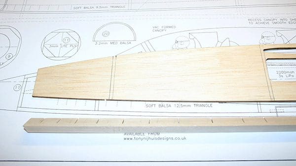
Begin cutting out the inner fuselage side pieces 6 and all Formers 7 through to 14.
Mark the location of the formers onto the left and right-hand side of each fuselage. Add strips of 19mm triangle balsa along the top and bottom edge of the fuselage. The top edge triangle will require some saw cuts at regular intervals to allow it to easily follow the tight curved edge of the fuselage.
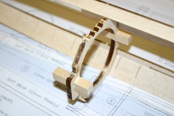
Holding Former 7 check that the fan fits correctly through the hole. For the 70mm Powerfun unit the opening in the former will have to be opened up very slightly.
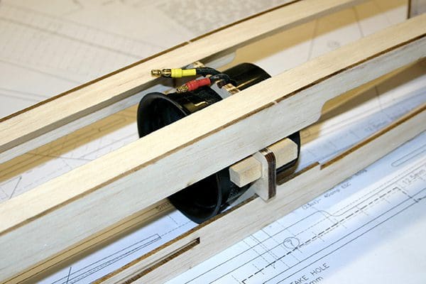
Glue the fan mounting rails onto Former 7 and secure the fan in position. The fan intake ring, which is taped onto the fan body by the manufacturer, will have to be removed to allow the fan to be fitted onto the mounts. Once fed through the hole the fan intake ring can be re-taped or glued back on.
Now make up the thrust tube while the fan unit is out of the model. The plan shows a cut outline of the thrust tube before it is rolled and it is made from 140-micron thick acetate. You will be able to source an A3 sheet of this on eBay or from a stationery shop. It is basically the thin clear plastic used on report covers. The easiest way to make the tube is to roll the end of the acetate around the fan unit, as tight as you can make it, as a straight tube. Then secure with a small piece of Scotch tape across the joint, at the fan.
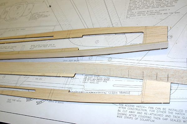
Now fit Formers 7, 8 and 9 to one side of the fuselage.
Fit the other fuselage side and add the remaining Formers 9 to 11.
Then slide the rolled tube in from the rear of Former 10. You will have to fold the tube in on itself but as it slides through it should pop round again. Gently ease the tube over the fan unit by 12mm or so, making sure the motor wires are exiting smoothly through the slot that you have made in the tube. If you have positioned the wiring slot correctly the tube’s seam should run along the bottom of the fuselage.
Finally run a piece of tape along the joint’s length, making sure the tube is pressed hard against the inside edge of Former 10. Use a couple of dobs of hot glue, one on the top and one on the bottom, to secure the thrust tube to the fan casing and two dobs against Former 10. That’s all the glue it needs!
I would suggest at this point that you loosely fit the ESC and check that the fan’s motor rotation is okay.
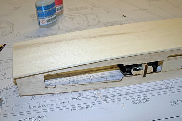
Sheet the top and bottom of the fuselage with 5mm sheet balsa.
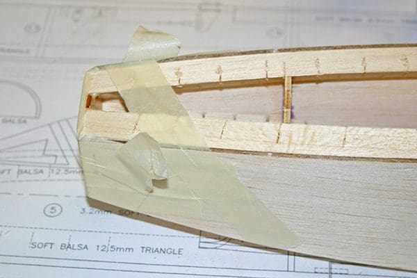
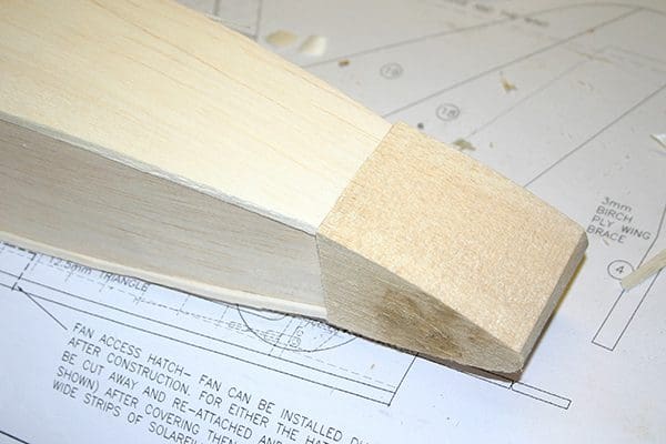
Make up the nose block using laminates of 12mm balsa or scrap 8mm balsa from the sheet wing stock. Make sure you cut the side profile of the nose block as shown on the plan and glue the nose onto 11.
Now for the ‘shaping’ exercise, so make sure your razor plane has a new blade in it…!
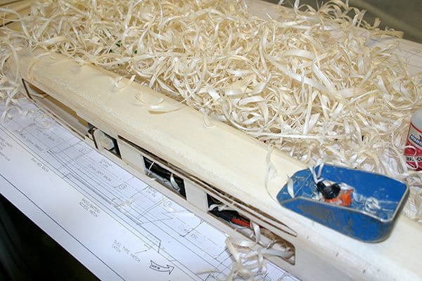
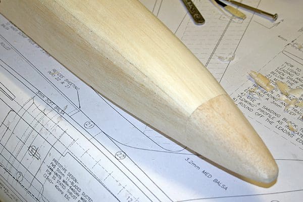
Please remember that there is a lot of shaping around the nose and the triangle balsa is there to be cut into to create the smooth radius curves of the Gnat, so don’t scrimp on the shaping. Use a razor plane to profile the square edges of the fuselage and then use a sanding block along the complete length of the fuselage.
Use the former profile shown on the plan to gauge the correct profile of the fuselage along its length. As you profile around the wing slot, you will have to trim away some of the triangle that covers the slot.
Now mark the positions of Formers 12, 13 and 14 on each side of the fuselage. Note that their height position is quite critical, so make sure you check and re-check their positions before gluing. Also note that Former 12 is sacrificial, which means the former is discarded once the model is built.
Make up the fuselage intake sides (15) from 3.2 mm balsa. The inside edges of the fuselage side should be lined with 12.5 mm triangle at the positions shown on the plan. Again, saw cuts will need to be applied to the triangle to aid bending of the balsa.
The intake sides can now be glued into position against the formers. The rear of the intakes should be sunk into the main fuselage 6, with the rear edge sitting 3mm proud of the main fuselage.
Now sheet the top and bottom air intakes. Use a piece of 3.2 mm balsa sheet as a fillet to blend the intakes smoothly into the main fuselage. You will need your sharp razor plane again to profile the square edges of the intakes and the fillet at the rear of the fuselage. Then progress on to using a sanding block along the complete length of the intake.
Mark out the fin slot and cut it out in the top sheeting.
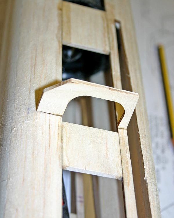
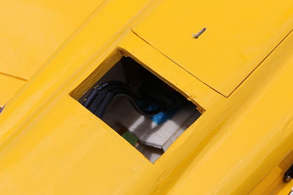
The fuselage access hatch can now be marked and cut out. Use a small hacksaw blade to cut through the bottom sheeting to the depth shown on the plans. Then, using a straight edge, cut through the side sheeting on each side to release the hatch. To retain this hatch, I used one of the SLEC small brass spring catches at the rear and a locating tongue made from scrap 3mm ply at the front.
Fin and tailplane
To make up the fin use parts 18 to 19 and glue them together. Profile the fin leading edge. Put the fin aside and only glue it into position once the model is nearing completion.
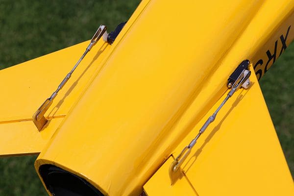
Now make up the tailplane using parts 16 and 17. Round off the tailplane leading edge and chamfer the elevator 17 leading edge ready for the hinges to be fitted.
Finishing off
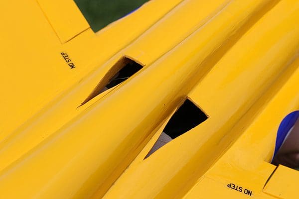
Don’t be tempted to reduce the size of any of the cheater holes, which need to be the sizes shown.
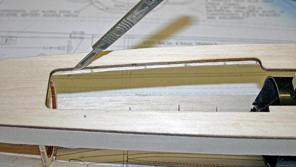
The wings can now be glued into position. They will need to be slid through from one side and a little fettling maybe needed, due to the anhedral, to get them to fit properly. The alternative, which I adopted and was less fiddly, was to cut across the top of the fuselage at the leading and trailing edges where the wing sits and remove this section of fuselage. This allows the wings to be glued into position and the top fuselage section can be glued back in place afterwards.
The tailplane halves can now be glued into position, making sure they are ‘square’ against the fuselage and parallel with each other.
The sacrificial former 12 can now be ‘forcibly’ removed from inside the air intakes and discarded. Using a 1/2” piece of tube wrapped with sandpaper as a profiling tool profile the corner triangle of the air intakes, so the intake lip is parallel all the way round, as shown on the plan.
The fin can now be added and the fillet pieces 21 and 22 added. Radius the edges of fillets 22 before fitting.
Now mark the position and add Former 20. Take a very soft piece of 1.6mm sheet balsa and wet one side only. Gently roll the piece over Former 20 and the rear fillets. Trim the bottom edges of the sheeting so it sits properly against the top decking. Once happy, glue the sheeting in place.
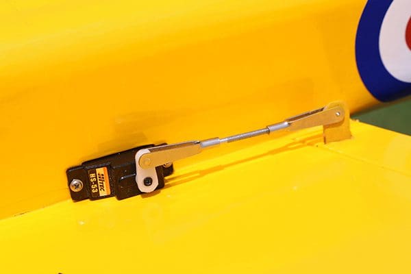
Mark out the locations of the aileron and elevator servos and ‘sink’ these into the fuselage sides, under the wing and the tailplane.
Finally, and most important of all, is the large cheat air intake hole in the underside of the fuselage and the two smaller ones on the top. Make sure you chamfer and smooth the entry leading edge of the openings. Don’t be tempted to reduce the size of any openings, which need to be the sizes shown as a bare minimum.
Covering
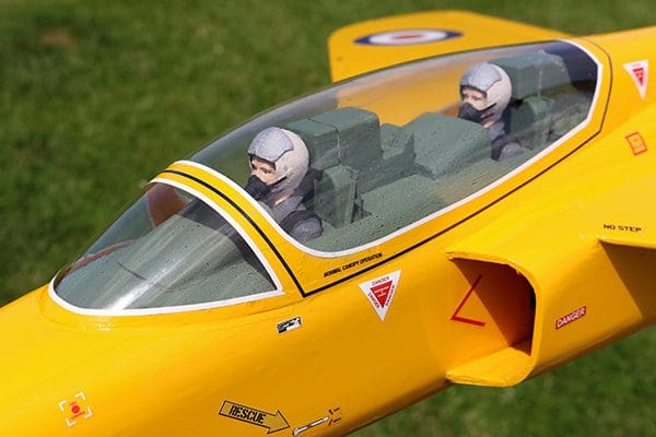
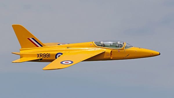
The prototype was covered using Cub Yellow Oracover from J Perkins. The ‘Yellowjacks’ decals set and pilots are available from the Tony Nijhuis Design website.
Fit all the control surfaces with SLEC flat flock hinges and secure with glue. Fit all the servos and control horns.
The C of G position can be achieved by adjusting the positioning of the 4S 4000mah LiPo flight battery. Do not be tempted to move the C of G back from the stated position! The battery was secured using self-adhesive Velcro.
The canopy can either be fitted before or after covering. I prefer to detail the cockpit, fit the canopy and then cover the model around the canopy, but it’s up to you.
Flying
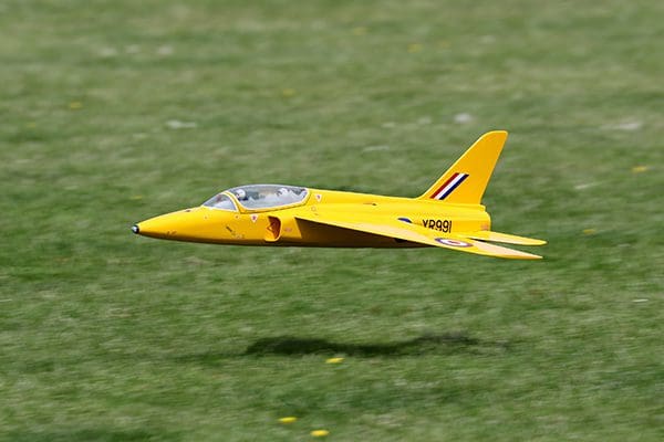
The first thing to note with these new ‘Midi’ jets is the wing loading is quite low so hand launching them is very straightforward. You won’t need a bungee or a catapult launch! You will, however, need a firm throw and make sure it is straight and level. I suggest, for its maiden flight, that you get a trusted helper to launch the model for you. This model is remarkably strong and if you don’t get it away first time it should survive.
Once the hand launch is mastered and the model is trimmed for flight it will get away with little fuss and very little control input. On calmer days expect to put in a touch of elevator for a second or two after launching.
When you get the model airborne, and assuming you have cut out the fan breather holes, you will notice how nippy the model is. Once the initial climb out has been executed and the model is fully trimmed out, you can easily pull back the throttle to half stick position and enjoy what is a very scale flying performance. You’ll find the model simply grooves and flies on rails, especially on a calm day.
All the classic jet manoeuvres can be done with this model, but you will need full throttle and speed for some, as the model doesn’t have the momentum to carry through manoeuvres such as big loops etc. Just remember to keep the routine smooth and keep what little momentum it has going.
Landings are very straightforward and generally you will run out of elevator control before the model will stall.
Don’t be tempted to adjust the C of G! The Gnat has been thoroughly tested and where it is shown on the plan is exactly where it needs to be.
The 4S 11-blade FMS fan units give an amazing punch and flight times are surprisingly good. So, expect a good 5 to 7 minutes depending on throttle use.
Turbine roar
I have to say that enlarging the Gnat was always on my agenda. But the outcome has far outweighed my expectations and, dare I say it, it is one of the best models in my collection. It’s small enough to sit in the back of the car, ready to go, but it looks, feels and flies like a turbine model, and sounds like one too! Since the 4S fan is running slower you really do have that lovely turbine roar, rather than a vacuum cleaner whine.
All in all, the 70mm EDF Folland Gnat is a cracking little model and flies incredibly well. You really will enjoy flying this one.
Datafile
Name: Folland Gnat
Model type: EDF Midi jet
Designed by: Tony Nijhuis
Wingspan: 33” (825mm)
Fuselage length: 36” (982mm)
All-up weight: 46oz (1.15kg)
Wing loading: 22 oz/sq. ft. (6.55 kg/sq. m)
Wing area: 0.175 sq. m
Parts, packs and further help
A vac-form set, combined CNC/wood pack and decal set are available from Tony Nijhuis Designs Ltd (TND), as are additional copies of the plan.
Website: www.tonynijhuisdesigns.co.uk
Email: [email protected]
Phone: 07563 518159 (9am to 4pm)
Finally, the forum at RCM&E’s web home – modelflying.co.uk – is a great way to chat with other builders and see their photos.


