The Limit EX plan can be purchased at www.myhobbystore.com
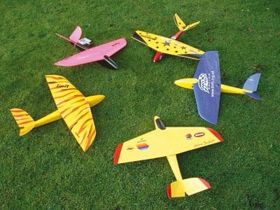
Many moons ago, I was out slope soaring, when one of the lads produced an entire model from his rucksack. One or two of the gang smiled knowingly as this tiny little aircraft – which was all of 18″ span – was committed to a 35mph blow. Of course, having seen it all, read the book and screen printed the T-shirts (sound familiar?), I turned my nose up in disdain and waited for it to get blown straight over the back of the slope… I’m still waiting.
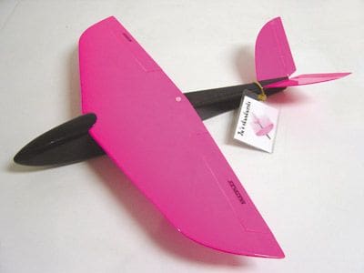
This whirling dervish just ripped the slope up, with vicious fast passes, a roll rate you couldn’t count and whip-cracking turns. On further investigation I found that this intriguing little model was loosely based on a German design and had been built by a mate of a mate, as always! I learned that the original design had a glass fuselage, foam wings and cruciform tail. The model being put through its paces, however, was of more simple construction – balsa box fuselage, built up wings and a simple V-tail.
Many weeks of pestering ensued but I could not persuade the owner to part with his toy. Instead, he let me take a few pictures and sketch out the proportions so that I may make one of my own. After getting back to the sanctity of my workshop, I transferred my sketches into Adobe Illustrator, and spent many a happy hour tweaking the outline – stretching the fuselage, lengthening the span, adding various design cues, then removing them – always returning to the original format.
In the end I settled for lengthening the originally stubby nose, to alleviate the necessity for so much lead, and increased the span by virtue of more shapely wingtips. As a nod to the original design she was christened Limit EX.
Article continues below…
Enjoy more RCM&E Magazine reading every month.
Click here to subscribe & save.
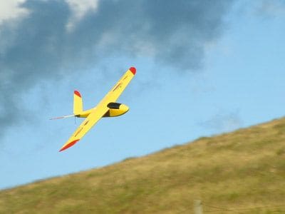
My own example created a similar impression on everyone who witnessed it, the response generally being, “Gorraavewunothem!” I built one or two as birthday and Christmas presents for the local slope royalty, and the gospel began to spread. The model’s performance became the stuff of legend, with one particularly amazing report of a flight in an 85mph wind at an F3F comp!
Eventually a couple of pics made it across the editor’s table, and into the hallowed pages of RCM&E via Andy Ellison’s column. The die was cast. I was deluged with requests for information about a kit or a plan – even ARTFs! After building another clutch of models for various people, I realised that the only way to reclaim my building board was to get the magazine in on the act. So here we are, with a blank sheet of paper and a remit to give you, the reader, the tools to craft your own. But where to start?
THE FUSELAGE
Select firm but light straight grained 3/32 balsa sheet and cut two fuselage sides as marked on the plan. Nothing too hard mind you, as the fuselage is gently curved from nose to tail.
Article continues below…
It’s more important that the fuselage stock is evenly matched, to avoid a ‘balsa banana’.
Once cut, lay the sides back-to-back on your building board (to avoid making two left or right panels) and add the balsa quadrant with a few drops of cyano. This provides the meat from which we need to carve a nice round shape later. At this point locate some scraps of hard 3/32 sheet to make the three simple formers. The corners of F2 and F3 must be removed to fit over the quadrant.
Mark the vertical centre of each former and tack in position on one fuselage side with a dot of cyano. Don’t make the joint too strong at this point, as you want to be able to make ‘eyeball’ adjustments later. Accurately position the second fuselage side over the first and tack once again with cyano.
Mark a straight line on your building board and place the fuselage over it, aligning the marks on the formers with your line. Sand a chamfer in the quadrant at the tail seat area and draw the rear fuselage sides together, tacking once again with a dot of Zap.
To relieve the stresses in the curvature of the fuselage sides around the nose, make a succession of thin cuts vertically through the quadrant from F1 to F2. This allows the nose to bend more easily. Once everything is lined up tack glue F1 in place, but be wary of any unequal curvature in the fuselage – good wood selection will pay you back right now! Adjust as necessary and then run thin cyano into all the joints.
The upper and lower fuselage sheet is 3/32 balsa once again, with grain running from nose to tail.
Cut the entire lower skin slightly oversize and pin in place. Give the fuselage another really good eyeballing for straightness, and once you’re happy that all is as it should be, run thin cyano into the joints. Trim the excess with a sharp scalpel. Add the top sheet, from the rear of the wing seat to the tail seat, in the same manner. The cockpit area is cut slightly oversize, glued into position with trusty cyano, then a nose block cut and laminated from three chunks of scrap before being glued onto F1.
What we have now roughly equates to the Frankenstein’s monster of fuselages! With the help of a razor plane and Perma-Grit block we can quite quickly knock all the corners off and produce a stunningly rounded body and a huge pile of shavings! Don’t be shy with the sanding, but equally, don’t go crazy. A strong light -source placed behind the fuselage will often show the thin spots if you’re not sure. Finally, add the 1/8 ply wing holding down plate and captive nut. The fuselage can now be put to one side, whilst we turn our attention to the next job.
THE WINGS
Article continues below…
My original model featured a built-up flying surface, lovingly crafted from 1/16 and 1/32 contest grade balsa, with full depth shear webs, no spars and unidirectional carbon sheet laminated into the trailing edges. I read War and Peace from cover to cover in the time it took to build it…
Whilst deeply satisfying, the built-up wing takes ages to construct and is as tricky as a box of frogs to keep straight. However, if you can’t bear the sizzle of nichrome through polystyrene, the balsa version is shown on the plan. Anyway, those of us who can put up with the stigma of a foam wing will be able to use the root and tip rib as templates. This was the first time I’d tackled a foam wing, and I have to thank fellow glider nut Adrian Hopkins for cajoling me into production. He showed me how to construct a bow, and we experimented with different foams and temperature ranges. The best cores were from blue foam, being quite rigid, with pink (Polyfoam) being a close second. The pink foam tended to warp after cutting, the eventual solution being to leave the cores in their shucks and place some weight on top for a couple of minutes, until the foam’s temperature had stabilised. Any good insulation company should be able to provide a range of foam products. I purchased an 8ft x 2ft x 50mm sheet of Polyfoam for around a tenner – although I had to cut it in half to get it in the car!
ONWARD AND UPWARD
All the models I’ve built thus far have had 1/32 balsa sheeted wings. It’s lovely and light, but the drawback is that it’s very easy to sand straight through. Obechi veneer would be equally good I guess. Prepare the sheeting slightly oversize and attach with Copydex, thinned with a little water, and brushed onto both the cores and skins. If left for a few minutes Copydex makes a really good contact adhesive; application of heat – if covering with film later – increases the bond further.
Trim and sand the cores before adding the firm balsa leading edge and balsa tips. Leave to dry overnight and then carefully sand the leading edge and tips to section. Butt join the panels with five-minute epoxy, then measure and cut a 1/8 slot for the ply joiner. Employ the five-minute epoxy once again to glue the joiner into place and trim / sand once set. Note that we have not removed the ailerons yet. This helps to keep the wings nice and straight.
Okay, here goes: Mark out the ailerons on each panel and carefully remove them with a sharp scalpel. For a full belt and braces job, face all the exposed foam with 1/64 ply or, do as I do – leave it unfaced and cover with film later.
Article continues below…
Turn the wing on its back and mark out, then cut the runs for aileron torque rods – these are a simple bending job from 2mm bike spokes or piano wire, with some short lengths of old Biro inner for bearings. The ailerons are top-hinged, so you’ll need to get the torque rods as close as possible to the top skin. Mark the position of the torque rod on the aileron and bore a hole in the foam to let in another length of biro inner; this locates the wire after covering. Position your aileron servo just behind the joiner, and let it into the wing.
Pushrods are from scrap 1.5mm piano wire, with a ‘V’ bend in one rod to facilitate trimming the aileron neutral position – there are no clevises for adjustment. The horns and pushrods are connected with short lengths of heat-shrink, which is a very neat idea and one that, sadly, I can’t take credit for!
Locate the wing accurately on the fuselage and mark the positions of the locating dowel and single nylon screw. Add a small disc of 1/64 ply over the wing bolt hole to spread the loads and glue in the locating dowel with five-minute epoxy. An easy way to mark the position of the locating dowel hole in the fuselage is to put a dot of paint on the end of the dowel and slide the wing into position carefully. The resulting mark on F2 gives a reasonably accurate drilling guide. I tend to drill undersize and then open up carefully with a needle file to get a really accurate fit.
TAIL FEATHERS
The Limit’s V-tail is cut from very hard 1/16 sheet. Join the panels at an angle of 110° as this gives a good compromise between elevator response and directional stability. Once joined, offer up to the tail seat on the fuselage and sand the exposed quadrant balsa until a nice fit is achieved. Be careful to maintain a 0-0 incidence with the wing seat for its particularly easy to get this wrong. I find a length of piano wire butted up to the V-tail panel joint gives a good visual indication of alignment. Tack in place with cyano and add a small balsa fairing to blend the tail into the fuselage top sheeting. The elevators are driven with simple 1.5mm wire torque rods let into each elevator half and cyano glued into place. They are more than strong enough! A simple forked pushrod will suffice to drive the elevators, connected with heat-shrink once again, there being little space for clevises, etc. Make sure both elevators and pushrod are set to neutral before shrinking though! Finally, a dot of cyano on the ends of each piece of heat-shrink makes a really secure job.
So, now we’re ready to cover. I’d recommend a proprietary film finish if you just want it done quick and smart. Alternatively, if you’ve more time and enjoy a little glass-work, then a 1/2oz cloth finish looks fab. If you’re going down the film route, remember that those wing skins are very thin and the foam can be easily damaged. My favoured product is Profilm, as it’s easy to stretch around the compound curves of the nose. Control surfaces, incidentally, are attached with Sellotape Diamond, which is crystal clear and, cunningly, resistant to UV light.
RADIO INSTALLATION
My prototype had a servo on each elevator, but having flown another model with a single servo driving both elevator halves, the benefits of rudder control proved minimal.
Save some beer money and use a single servo is my advice! The elevator servo can go anywhere between F2 and F3, but make sure it doesn’t clash with the aileron servo.
A 400mAh NiCad fits neatly in the extreme nose, reducing the need for a lump of church roof to balance, with the Rx wrapped in foam in the remaining free space just aft of F2. Add a switch if you have room, though quite honestly I never bother as it doesn’t take long to remove the wing and plug the NiCad directly into the Rx. As a point of interest all servos were 9g types, giving more than enough grunt for all eventualities.
UP, UP AND AWAY
Take it easy to begin with. Start with a centre of gravity at 55mm from root l.e. and trim aft to taste, in very small increments. This setting should promote a ‘zoom climb’ with speed, which indicates a forward C of G – and a margin of safety!
Control throws should be small, typically 5 – 6mm on ailerons in both directions, with differential trimmed to suit your preference for roll and turn performance.
Elevators are very critical – start with 4mm in both directions.
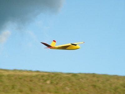
The model gets very small, very quickly. Try to fly it smoothly, with big manoeuvres, at least until you’ve got comfortable. Also, try not to hang on the elevators, let the wing work. Sharp elevator inputs will result in vicious flick rolls. You have been warned.
Minimum wind speed for this little baby is about 10mph and upwards. And I do mean upwards. Try 85mph as the highest recorded! Enjoy – you know you want to…
DATAFILE
Name: Limit EX
Model type: Aerobatic slope soarer
Designed by: Julian Beckett
Wingspan: 18″
Fuselage length: 191/2
All-up weight: 8oz
C of G: 55mm from root l.e.
Recd No. channels: Two
Control functions: Aileron and elevator
Control surface travel: Aileron – 5 to 6mm each way, Elevator – 4mm each way
Built or flown the LIMIT EX? Why not leave your review
here.


