Danny Fenton describes his build of a DB Sport & Scale semi scale kit
Regular ‘Make It Scale’ readers may recall that I had purchased a DB Sport & Scale Auster Autocrat from an advert in RCM&E. The remit was for a fun model to try a few techniques I had been musing for several months. In fact, one had been on the cards for a few years! My mind works quite slowly sometimes but I do get there in the end.
The things I want to try are:
Enjoy more RCM&E Magazine reading every month.
Click here to subscribe & save.
Adding Frise ailerons
Adding flaps
(Are you sitting down?) An IC four stoke engine!
AN OLDER KIT
I have a few other ambitions, but they may not happen; we will see.
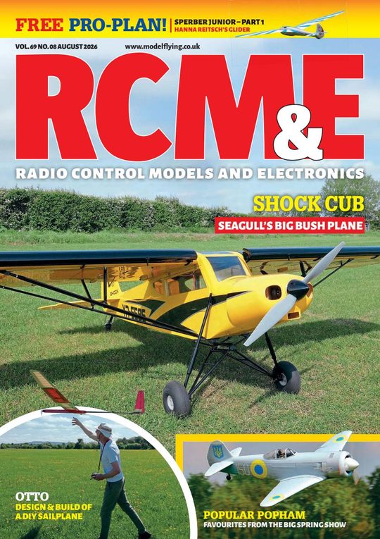
I dropped a mail to Richard at DB Sport & Scale, and he informed me that, going by the artwork and lack of wheels (now included), the kit I had bought was at least seven years old. Richard said that the kits are continually being developed and updated, so what you see here may not reflect the current kit.
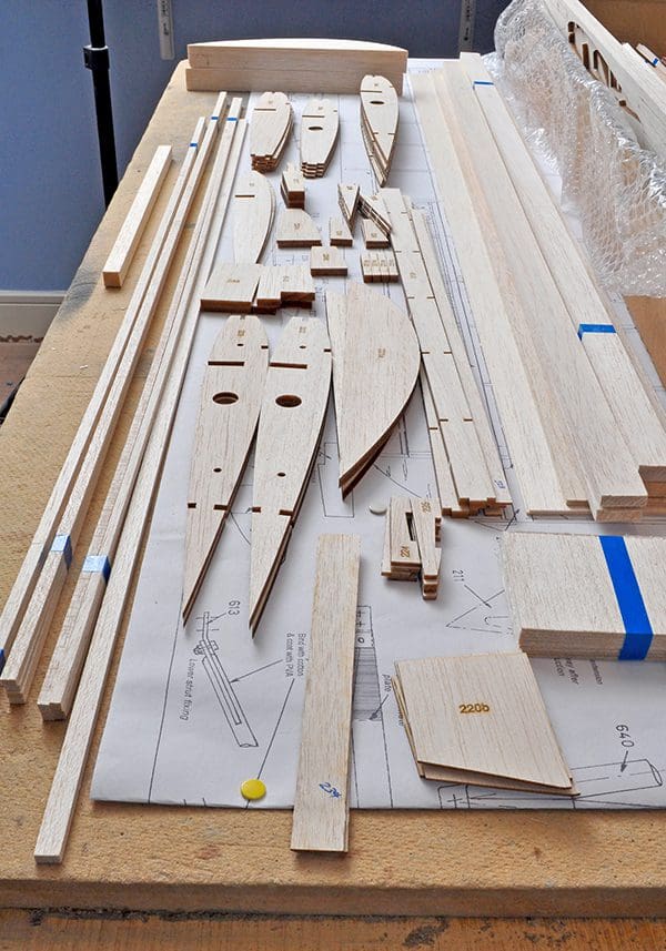
The kit is well cut and only a few of the harder sheets of wood needed some help to cut right through and release the parts. I must say, I have not found one part to be missing. Some are a bit dubious on size but all-in-all it’s an exceptionally good kit. The instructions leave a bit to be desired as they are light on diagrams and no pictures. I have blogged the build on the Modelflying forum and others have chipped in with their builds, so perhaps if you are contemplating one of these that will help.
This is not meant to be a review and I am sorry if it is leaning that way. But I must say everything is included, which is great – sheet wood, strip wood, hardwood, piano wire and glazing. Even closed loop wire and clamps. Very impressive. However, I was surprised that there is no tank.
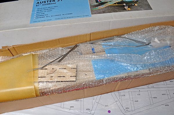
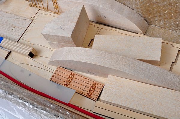
As can be seen in the accompanying pictures some of the wood was harder in areas than in other areas. This is difficult for the laser to deal with and some parts had to be ‘teased’ out of the sheet with a sharp blade. I would prefer this to the softer areas being scorched!
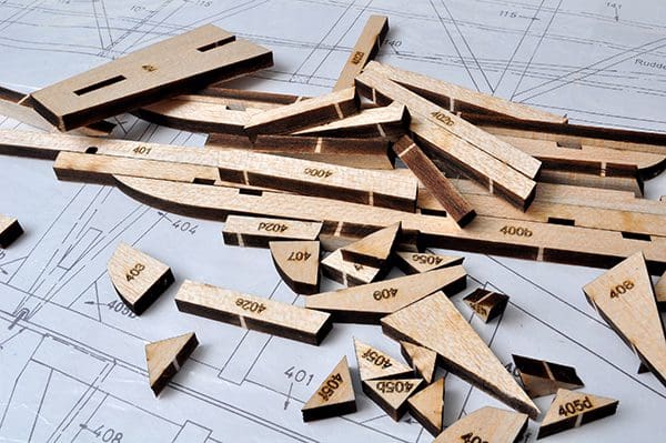
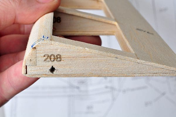
All the parts are numbered, and this makes grouping bits together for, say, the wings or fuselage, easier. My one complaint would be that the plans do not include outlines of the bits. This makes identifying, say, part 405b from a simple number on the plan as you really have no idea of what shape you are looking for. Not so bad, but woe betide a part being missing; you cannot make the part.
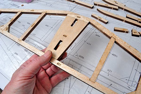
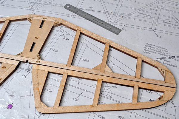
TAIL FIRST
I built the tailplane first and this was very straightforward. However, the fit of the parts was not amazing, but I am very fussy. The gaps were not as tight as I would like, as though the kerning for the cut had not been allowed for. I would prefer the outline to be laser cut and the joining longerons cut by the modeller. This way you gain better satisfaction and only have yourself to blame for any sloppy joints. Having said that they weren’t so bad that I spent time re-making the parts.
I had already decided that I would break away from the plan in certain areas; this was not going to be a true scale model but semi scale. However, there were a few areas where I couldn’t pass up the opportunity to stamp my mark on the model.
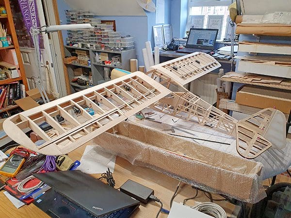
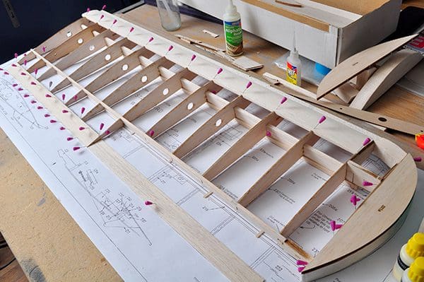
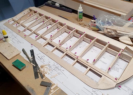
WING WORK
I was looking forward to building the fuselage so I thought I would deal with the wings first.
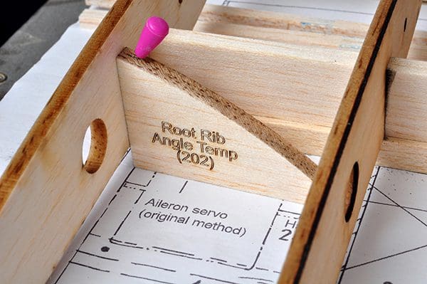
The root rib template may catch you out as it angles the rib in reverse to a conventional model with dihedral. This is because the root rib on the fuselage angles steeply due to the fuselage being wider at the midriff than the top, where the wings mount.
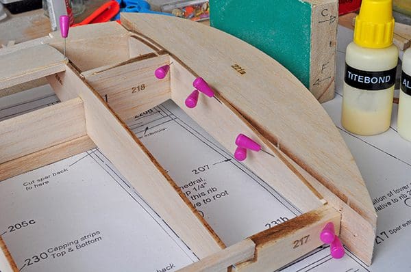
The wingtip is laminated from several lumps of balsa and is odd when viewed on a three view. The tip is nearly flat across the top, but heavily undercut. You need to study some photos to get it close.
The model is not exactly accurate here and it should have additional ribs instead of block, but it is a stand-off scale model after all.
I was going to change the ailerons from top hinged affairs to Frise, so I added more wood to the leading edge and top parts of the stock ailerons to give me some wood to sand into.
With Frise ailerons the hinge point is on the bottom surface of the aileron, some distance back from the leading edge. The idea is that the aileron leading edge offers little drag when the aileron is deflected downwards.
However, when deflected upwards the leading-edge projects into the airflow dramatically. This means the down going wing (up going aileron) creates much more drag and yaws the aircraft into the turn. This means less rudder is needed to balance the turn.
The wing retention and spar arrangement on a high wing cabin model are a bit of a nightmare. The problem is hiding the retaining system and those big, obtrusive wing spars.
The proper way to do it is to use a structure of carbon tube to replicate how the full size is fabricated. I had hoped to do this, but the ply bulkheads were too far integrated into the design and a new fuselage would have been easier. (Remember this is stand-off, I kept saying to myself!)
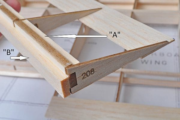
The way DB Spot & Scale got around the spar and wing retention was by using piano wire joiners. The piano wire is affixed across the top of the two main cockpit formers.
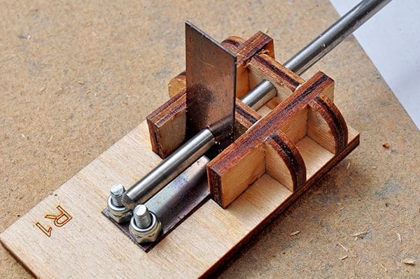
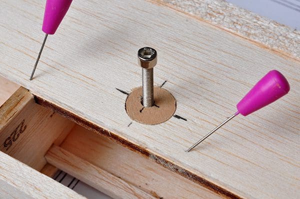
The wing retaining system is very clever and involves a sprung steel clamp. It does work and many have used it. The first time I tried to release the wings, however, I struggled. I envisaged a fraught time at the field with wings stuck on, so I changed my mind and cut the wings apart and removed the spring steel plates.
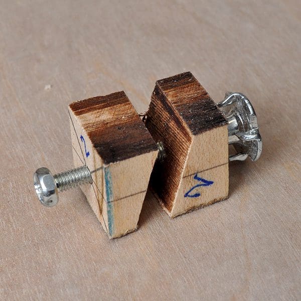
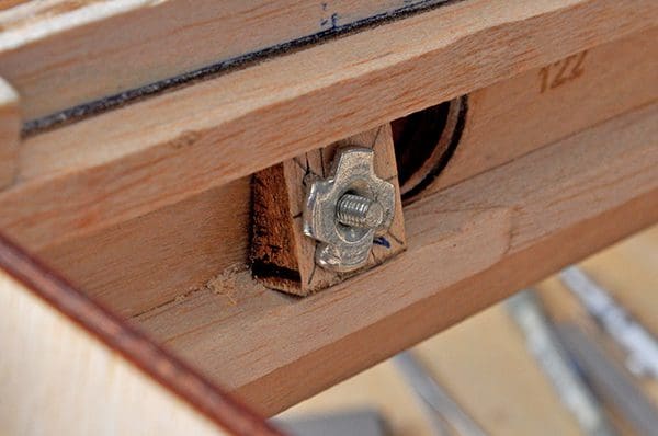
Wing retention is done using a Merlyn clamp in each wing root, which is shown in the pictures below.