
Shaun Garrity steps back in time and modifies an attractive tailless design for electric power and three channel radio control.
words & photos » Shaun Garrity
Back in the late 1940s one SMAE competition used to get the creative juices flowing in aeromodellers. Known as the Pterodactyl Cup it was specifically for tailless power models, with contests held at Fairlop and Eaton Bray. These were free flight aircraft with no radio guidance, so stability and excellent flight manners were crucial.
Enjoy more RCM&E Magazine reading every month.
Click here to subscribe & save.
The competition winning Manx Queen was designed in 1947 by A.H. Wilson (they were very formal back then – no first names) but what made this model very different is that it used an L.S.A.R.A. wing section. A quick look at the plan will make you think it’s been drawn incorrectly. The ribs appear back to front but this is quite correct.
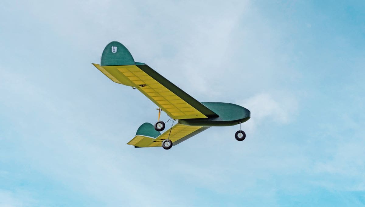
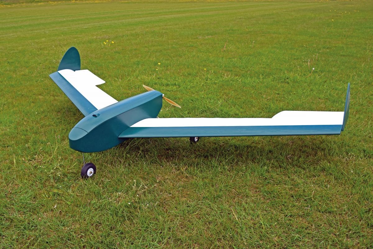
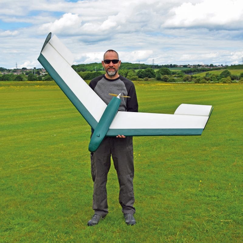
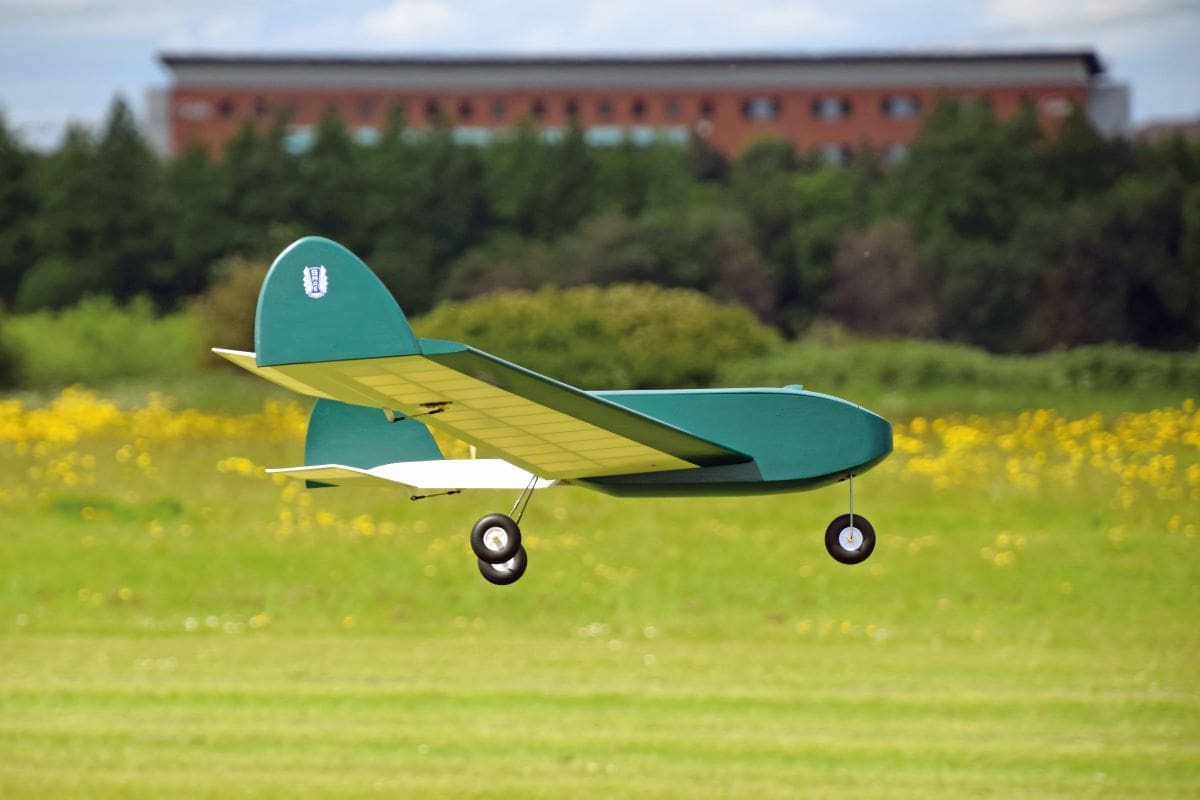
As mentioned, the original model was designed for free flight and powered by a Forster 29 spark ignition engine. But I’ve updated it to e-power and R/C. It’s no high-speed aerobat (the clues in the name of the wing section used, as you’ll discover in the next section) but is an absolute pleasure to fly and it cuts a very distinctive profile in the sky. In fact it wouldn’t have looked out of place in an episode of Flash Gordon. (You may need to Google that reference if you are younger than 40 years old!)
A.H. Wilson’s original plans for Manx Queen (MA39) are available from Sarik Hobbies: https://www.sarikhobbies.com/product/manx-queen-plan-ma39/
L.S.A.R.A.
The Low Speed Aerodynamics Research Association was a group of individuals who wanted to investigate aerodynamic issues surrounding low speed flight. They used model aircraft because aircraft operating within this flight envelope generally utilise a low Reynolds number. The benefit of a low Reynolds number is the airflow tends to be laminar; higher Reynolds numbers generate turbulent flow. The Association’s aim was to further research and development within the full-sized aviation industry. Information on L.S.A.R.A. has been thin on the ground but thanks to the internet I’ve managed to dig up the following.
It was formed soon after the end of WW2. No doubt budding aerodynamicists were spurred on by the RAF’s success in defeating our enemies and Britain’s world beating innovation in aircraft design. L.S.A.R.A. wasn’t just a UK organisation though and it included several British Commonwealth countries. Its main goal was to disseminate research and knowledge gained from experiments in model and full-size aviation to the benefit of all. In January 1950 Aeromodeller an article was published which noted that the L.S.A.R.A. ‘had the finest equipment in the world for model research, including several wind tunnels for the evaluation of aerofoils.’
Looking through old copies of Aeromodeller and Model Aircraft I came across several articles published by the group. In fact, Peter Chinn was a member. For those who are not familiar with the name, Peter was the king of model engine reviews in RCM&E (Radio Motor Commentary) and Aeromodeller. He published a number of books on the subject and aeromodelling in general.
If you want to read a very comprehensive overview of the L.S.A.R.A. and its activities, then have a look at the web article penned by Adrian Duncan. It’s an excellent and informative piece: www.modelenginenews.org/people/lsara.html
TIME TO BUILD
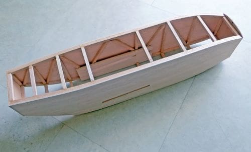
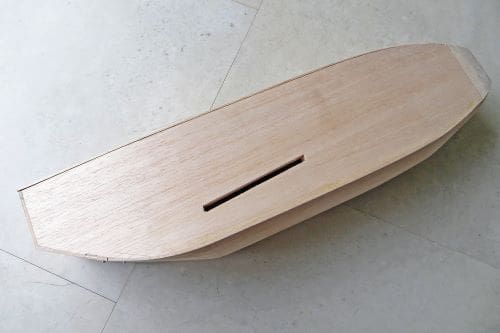
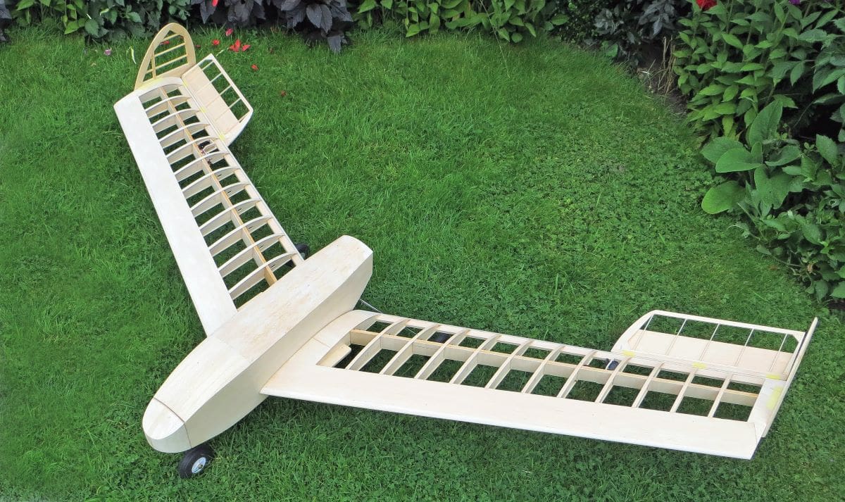
Manx Queen is a very traditionally built model and is probably not ideal for the novice unless you have some help available from a seasoned aeromodeller. I would suggest starting with the fuselage as everything hangs off this.
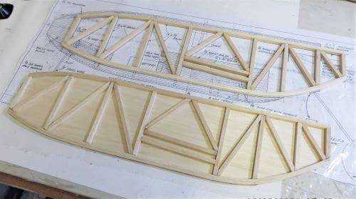
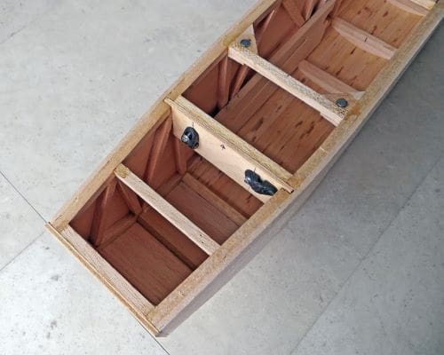
First, make the side frames from medium 1/4” square balsa, building both at the same time, one on top of the other; this ensures you get two identical items. Don’t forget to use grease proof paper or the backing sheet from heat shrink film between the two so they will easily separate.
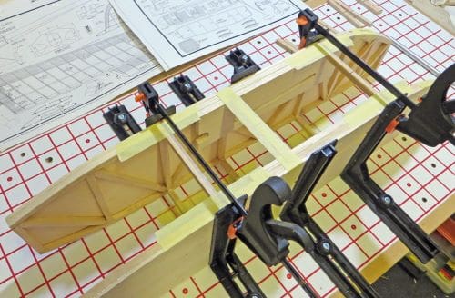
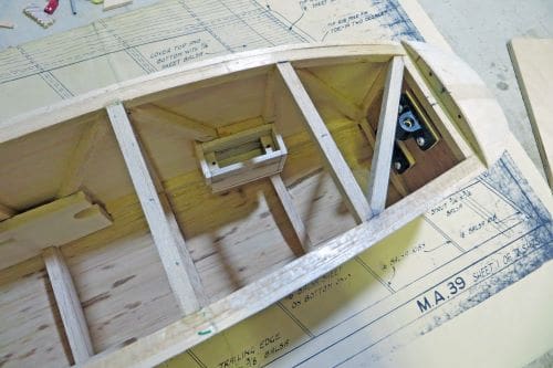
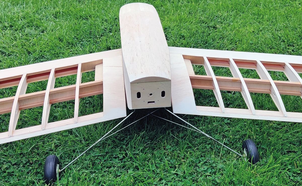
Sheet the frames with 1/8” medium balsa as shown on the plan and check you have a pair and not two identical sides! When dry glue the formers and spacers to form the basic fuselage box, adding the curved bottom and top formers, plus the wing strengthening pieces for the ply wing tongue and nose leg assembly. Ensure that the fuselage isn’t twisted. If going electric the engine bearers are not required. Note also that the top of the fuselage is the access hatch so only tack glue all the upper curved formers in place on the spacers when building this part to make removal easier when finished.
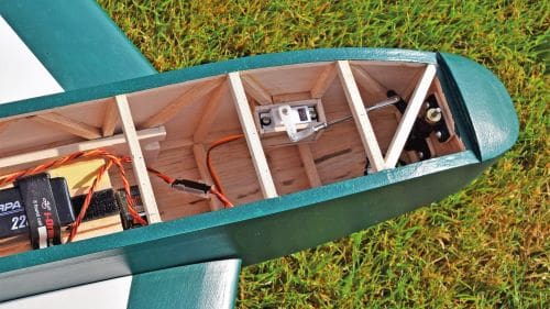
Now’s the time to fix the undercarriage in place. I used saddle clamps as opposed to stitching. To form it a wire bending jig makes the job slightly easier, but a vice will do fine. The suspension system detailed for the nose leg works well and will help prevent damage in the event of a heavy nose wheel landing. However, the downside of the original set up is that it isn’t steerable, so this makes ground handling interesting (actually it’s non-existent!) Reference the photos to see how a modified steerable nose wheel can be used in place of the original one. If you can find some vintage Trexler wheels they will add to the look of the model, but modern ones are fine if the tyres aren’t too hard.
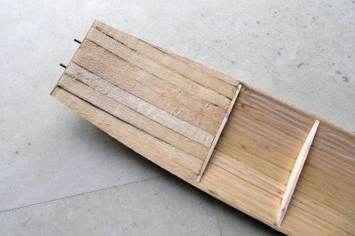
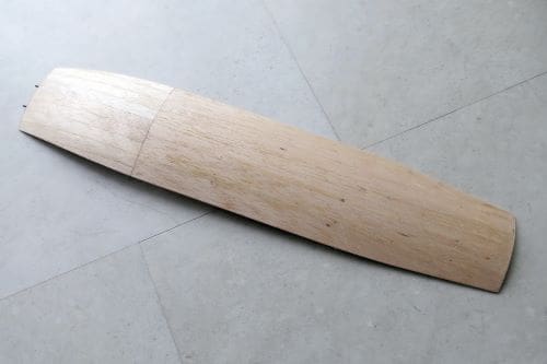
Since the profile of the upper and lower fuselage is a compound curve it needs planking as opposed to sheeting. If you’ve never tried this technique, it’s not difficult. Start by cutting some medium 1/8” balsa sheet into 3/8” strips. Commence gluing the strips lengthwise from the centre and working out, trimming them as required. The edges of the strips may need shaping slightly to form a perfect fit. I would use aliphatic for the edge joints as this will sand far better than PVA, using a combination of aliphatic and cyano (or pins) to hold the planking strips in place until dry. If you need more info on planking a quick internet search will bring up various forums and videos.
Glue the soft balsa nose block in place, shape, then sand the whole fuselage so it’s ready for covering. Glue in the 1/4” wing tongue. Don’t use lite ply for this piece, it needs to be traditional ply. But you could use two pieces of 1/8” ply laminated together to make the job of cutting it out a little easier.
WINGS
As mentioned in the introduction this model uses a very unusual wing section. Fear not as the model flies extremely well, so don’t be tempted to try to modify things. The designer knew his onions. Other than this it’s a traditionally built wing.
For each wing panel start by cutting ribs using the good old sandwich method. Make a tip and root rib template from 1/16” ply then put 12 x 1/16” balsa and 1 x 1/8” (for the tip) blanks between the ply ribs and cut and shape them from across the root to the tip to get tapering ribs. The two root ribs can be cut separately from 1/8” hard balsa. Accurately mark the position of the four spars and notch all the ribs at the correct angle so the spars don’t distort them. The trailing edge needs washout building in at the tip. To achieve this place the 1” x 1/4” hard balsa trailing edge on the plan (note that the rear needs chamfering to the profile of the ribs) and glue all the ribs in place on the trailing edge. The tip rib has two degrees of toe in, and the root rib needs setting at the correct angle to give the required dihedral. Pack up to 5/8” at the tip, ensuring the root rib is flat on the building board. Glue on the 3/8” square leading edge.
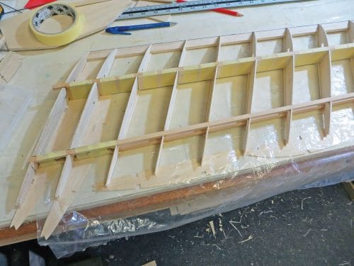
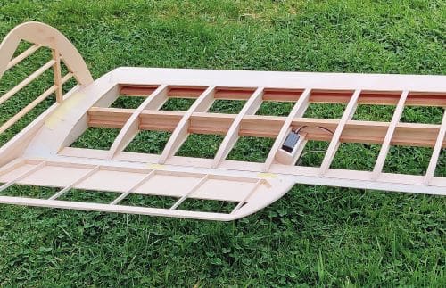
Now add the spars. I used spruce instead of the original balsa ones shown and to improve the rigidity of the wing I added extra vertical 1/16” balsa shear webs, upper sheeting for the leading edge, tip, root and rib capping etc., ensuring you don’t introduce any unwanted warps and maintaining the washout.
Wing tongue boxes need building next. Make sure you have faced the spars with the 1/16” ply shear webs where detailed. Make a dummy tongue from hard balsa for this task, coating it in Vaseline, wax or silicone grease. This allows the hard balsa 1/8” sheet and 1/4” square rib stiffener to be pressed tight against the tongue for a perfect fit without fear of the tongue being glued permanently in place.
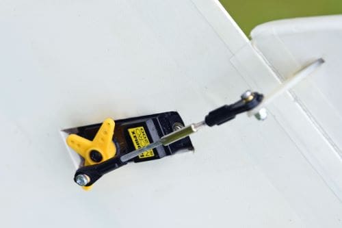
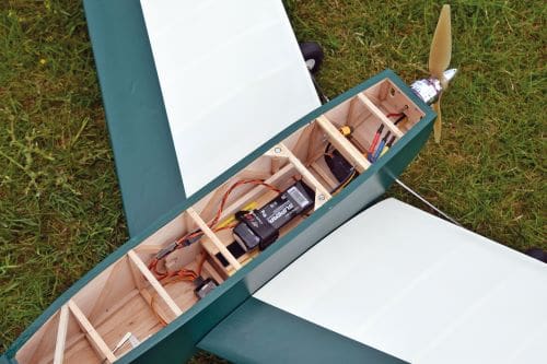
Flip over the wing and sheet as required, again ensuring that you maintain the 5/8” washout and haven’t forgotten to add the piano wire wing retaining hooks. One final job is to build in the mounting points for the elevon servos; if you look at the relevant photos you can see where and how they are mounted. Then sand each wing panel ready for covering.
FINS
The fins are hardly worth a mention but use medium balsa so they won’t warp easily. The aluminium strip for setting the elevon incidence isn’t required for radio control. I would cover these before fixing in place as it’s much easier.
ELEVONS
Again, hardly worth detailing. Build them from medium balsa and ignore the note about aluminium hinges on the plan and sand to the profile shown. The elevons need attaching with suitable pin hinges, CA hairy hinges or they can be stitched.
Performance is improved if you seal the gap between them and the wing with tape, but this is not absolutely necessary. Again, cover them first before fixing to the wing and don’t forget to insert a hard point where you intend to mount the
control horn.
RADIO & POWER TRAIN
Only three channels are required for the Manx Queen, for the elevons and throttle. Years ago, I modified my first Manx Queen to have twin rudders on the fin but to be honest it was a waste of effort. However, a worthwhile upgrade is to install a steerable nose wheel for ground handling, so a further channel would be required for the servo.
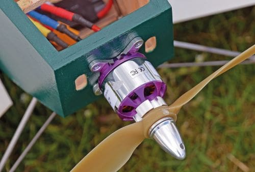
One benefit of an electric motor over most IC engines (Cox reed induction style motors being one exception) is that you don’t need a reverse pitch prop, just a regular one with the motor rotation reversed. So, you can fit a wooden prop for that old school look.
There’s no shortage of space in the fuselage for the electronics so there are no excuses for a scrappy radio installation.
For power the set up shown in the Datafile works well.
COVERING & FINISHING
Solartex or Oratex is perfect for this model, but I’ve also used cheap polyester cloth from a dressmaking shop with great success. Having no adhesive, you’ll need to apply something like Deluxe Materials Cover Grip where you want the cloth to stick to the airframe. It takes dope well and shrinks a small degree with heat. Another option is Mylar film (Doculam) with tissue (or even silk) over the top for a totally retro look.
I had plenty of Solartex in stock, so this was used. The finish was a little different, using matt emulsion paint applied with a roller, then sealed with a water-based floor varnish. I’ve had mixed results with water-based floor varnish though. Some brands seal well while others still appear a little porous and when rained on they go milky, clearing up again when dry. If this happens it’s easy to resolve; just apply a further coat of polyurethane varnish. Satin is my preference to gloss. This is a very inexpensive, easy and quick way to finish models. I’ve even used it on 1/3rd scale aircraft in the past. Obviously, for petrol and glow models exterior polyurethane varnish needs to be used as its fuel proof.
If you want to use heat shrink film the wings are rigid enough so no problems will be encountered.
TIME TO FLY
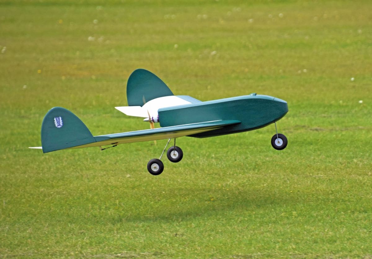
Check the C of G, elevon reflex, then the throws and direction of the control surfaces. Manx Queen was designed as a free flight model that would take off from the ground unaided, so assuming there are no warps she should get airborne without any stick twiddling.
As previously described the model uses a wing section specifically conceived for low-speed flight but that doesn’t mean it’s not fun to fly and she can be coerced to perform some mild aerial gymnastics. Manx Queen would also make a great FPV / camera platform. She cuts an impressive and futuristic profile in the air and doesn’t look like a 1947 design.
Landings really don’t need any interference from the pilot. Line her up, reduce the throttle and a landing will happen, usually without even needing to flare. It’s a very different model in terms of looks and wing section but you won’t be disappointed unless prop hanging and low inverted passes down the strip is your thing.
If you build one, then don’t forget to send me some pictures. There’s a good chance they’ll end up in my Retro Ramblings column: [email protected]
DATAFILE
Name: Manx Queen
Model type: Vintage tailless
Designed by: A.H. Wilson
Construction: Traditional balsa & ply
Wingspan: 72” (1829mm)
Weight (exc. LiPo): 3lb 8ozs (1.6 kg)
Functions (servos): Elevons (2), Throttle (ESC), optional steerable nosewheel (1)
Motor: 4-Max PO-3536 -1000kV
ESC: 40A
Prop: APC 10 x 5
Battery: 3S 2200mAh LiPo
CONTROL THROWS
Reflex: 30mm
Throws: 20mm up, 10mm down


