
- This review was first published in 2003, the kit has since been re-issued in an all-silver scheme and currently enjoys limited availability.
Graupner’s semi-scale Taifun follows the recent trend towards a slightly more up-market ARTF, with high build quality and additional features such as flaps and retracts. Actually, I’ll let you into a secret: I’ve not yet built a model with both flaps and retracts, so this was an exciting prospect for me.
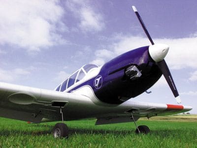
At 63” span, the Taifun has a 14” root chord, a chunky fuselage, and .91 power. Overall, a very impressive ship that’s further enhanced by an above average build quality. As a club-standard modeller, I don’t mind telling you that I’d find it hard to produce an airframe this good. At first sight, there doesn’t seem much to do. The large fuselage is covered with decorated, pre-panelled, pre-riveted film, and the traditionally built wings are supplied with pre-fitted retracts, ready hinged flaps, and similarly prepared ailerons. Even the tailplane halves (suitably adorned with trademark Messerschmitt struts) are ready hinged and covered.
QUICK BUILD
Airframe assembly is very rapid. All the wood fits, joints are well cut and well matched, and the visible internal woodwork is first rate.
Enjoy more RCM&E Magazine reading every month.
Click here to subscribe & save.
In truth, you could join the wings and fit the tailplane in about half an hour if you wished, though it is perhaps better to fit all the servos, horns and links first. Since the model is already beautifully covered, it will also be necessary to line your bench top, and possibly the wall behind it, with polystyrene (or similar) to stop that dreaded hangar rash.
- The main areas of airframe assembly are:
- Joining the wings (a breeze).
- Fitting the tail, struts, and fibreglass lower tailcone (also a breeze).
- Trimming and fitting the canopy.
- Fitting the steerable tail wheel.
The more demanding areas of ARTF assembly (as always) are:
- Fitting the engine.
- Making a good job of the cowl and its apertures.
- Completing the radio installation.
However, all pushrods are made to length and all connectors are of the quickfit type, so everything just goes together like a breeze.
TAKE YOUR TIME
The whole model took me about two weeks of evenings to complete, and could undoubtedly be built much more quickly. But then, I am a bit dilatory. This is such a superb and impressive model that you just want to take more than normal care in the building – it also represents a considerable financial investment, so you’ll want to minimise any chances of a cock-up caused by some slight inattention to detail.
POWER AND CONTROL
When building such a model, you need to sort out your power and control requirements at the outset. I took the lazy option and called Motors and Rotors (UK distributor) to quiz them about their prototype; Dave Wilshere cheerfully answered all my questions. He’d used an O.S. .91 four-stroke with a 14 x 6 APC nylon propeller, and said this gave it “buckets of power.” He reckoned a .70FS would do just fine, and so did I. That said, I still went out and bought a .91!
Dave used JR radio, as opposed to my Futaba, but recommended a Hitec retract servo (HS 75BB). My own preference here was a Futaba FP-5136G, but in truth, either is adequate. On the subject of servos, it’s worth noting that you’ll need to buy no less than eight for the various control functions: Rudder (x1), elevator (x1), throttle (x1), aileron (x2), flap (x2), retracts (x1).
I’ve had some experience with multi-servo wings, and in my view, assembly at the field can be a bit of a pain.
Piles of connections must be made,and wires get strained before popping out all over the place. My way around this was to fit long extension leads to the flaps, retracts and ailerons – So long in fact that I could leave them permanently connected for storage, transport and flying. In order to stave off any possible interference, you may wish to fit ferrite rings to these leads; my alternative was to keep them well away from the aerial, and I’ve had no trouble at all.
In practice, it took me a whole night to fit all the servos: 32 grommets, 32 ferrules, 32 pilot holes, 32 screws, and eight servo arms. And that’s before you sort out all the quick-links, the adjuster connections, the tail-wheel fitting, and the positioning of the switch. By the end of the evening, you’ll have discovered more about servo-mounting hardware than you ever wanted to know. In terms of mental effort it’s a real no-brainer, but oddly satisfying.
A tiny issue presented itself here – one of the wing servo plates wasn’t routed out for the servo arm to exit. This took a couple of minutes to sort on the pillar drill, although I could have just chain-drilled and cleaned it up with a file.
SAFETY FIRST
Since the tailplane is in two halves, so too is the elevator. Snake outer tubes are pre-fitted, while the piano wire inners are cut to length and ready assembled; similarly, the rudder and tail-wheel assembly require two control runs.
In reality, all one really needs to do is make up connections via the supplied adjuster bars. These are little metal ‘hexagonal section’ bars, cross-drilled and tapped for three grub screws which, in turn, retain the two rear pushrods. So, for example, where you have two pushrods from the split elevator halves coming forwards to a single elevator servo, the hex adapter mates these up to a third, short single rod that connects directly to the servo. Two into one.
The way forward is to lightly clamp the control surfaces in neutral with balsa-faced bulldog clips, set the servo to neutral, and adjust the length of the pushrods through the hex bars. When all neutrals on the control surfaces and the servo are in place, you’re supposed to just nip up the grub screws with the supplied Allen keys – all very well, but after doing it I couldn’t face the thought of a rogue screw coming adrift in flight due to engine vibration, and thereby depriving me of elevator. With this in mind I went for a ‘belt and braces’ solution, and cyano-glued the grub screws. Then, using tinned copper wire, I soldered up the whole shebang so that slipping or unwanted disassembly became impossible.
Did I mention that you have to fit the control horns all by yourself? I mean to say…
RADIO
I put the NiCad, wrapped in foam, under the tank (as is my normal practice). Since the space for the receiver is vast, I put this behind the servos to the rear of the fuselage bay, tucked under the pushrod outers and packed out with ‘sprung-in’ lengths of B&Q grey foam pipe lagging.
A raw egg could survive in that little lot! Maintaining the all-important scale theme, one’s radio switch was internally secured with a bicycle spoke ‘remote’ push-pull connection on the opposite side of the fuselage to the exhaust.
Anticipating increased servo loads due to the undercarriage, I bought the recommended larger capacity 1400mAh NiCad, and had to agree with Mr Wilshere in his assertion that a separate retract pack just wasn’t necessary. In addition to boasting pre-fitted u/c legs, you’ll also find that the wheels on thismodel are on, and the pushrods installed. All very well, but would I get them to cycle smoothly? Could I guarantee a positive and sturdy lock-down? How would they deal with our grass strip at the Singing Kettle field?
In the end, everything was a delightful anticlimax – it all worked very well. It’s true that when up, the legs sagged a little with their own weight, but I reckoned that the positive lock-down was a price worth paying. It is vitally important to avoid stalling the retract servo up or down. A computer radio is a boon here, and my battered budget FF6 handled it well.
TO MIX OR NOT…
During the construction period, I was advised by clubmate Gareth Williams that, after the initial test flight programme, I should progress to more complicated flap / elevator mixing – and he’s right. In fact, I’m really looking forward to it. However, to begin with, everything was kept ultra simple: one channel to a ‘Y’ lead driving each aileron, and another channel to a ‘Y’ lead for both flaps. I drove the flaps from a rotary knob on the FF6, and thereby avoided fancy mixing, split channels, and problems with trying to use a bog standard 5-channel radio.
But, I’m getting a little ahead of myself. Completing the wing installation allowed me to take a break, and then spend many happy hours cycling and recycling the retracts. This was endlessly fascinating. My mates came, and they had a go too.
ENGINE ENERGY
I couldn’t afford an O.S., and wanted to try a Thunder Tiger .91 instead. ‘Crash’ Parry has one, and his is a cracker; At £129 it was an absolute bargain too… but first, I had to fit it.
Getting the lump in, and making a nice job of the cowl, is the biggest challenge on most ARTFs. I wanted to achieve that all-important sexy, smooth and scale-like ‘spinner to cowl’ transition, whilst hiding as much of the motor as possible. The supplied polyester fibreglass cowl is good quality, being well wetted out, and hallelujah! Unlike many, many, ARTF’s, its colour actually matches the covering. I was a happy man.
Meticulously translated English instructions, supplied with the kit, provide dimensions on exactly where to drill the engine mounting holes for a given motor. Now, this might not sound like much, but when you get down to it, the position accurately defines the relationship of spinner to cowl, engine to firewall, carburettor to firewall, and so on, all in one go. Consequently, I fitted the engine, cut cowl apertures for the rocker and needle valve, and mounted the whole lot in a single evening. A record for me, and I’m a notoriously slow builder.
Here’s a selection of salient points that’ll help when installing the engine:
You must fit the mount, the tank, and then the servos. I departed a bit from the words and music and made my servo tray removable because I know, sure as ‘eggs is eggs’, that if I ‘build-in’ a tank, it’ll eventually need re-plumbing.
Building notes suggest that you incline the engine to 45° inverted, which I did. This allows the whole exhaust, and most of the engine, to be neatly concealed within the cowl. Only the rocker box protrudes.
Four-stroke exhausts run very hot, so I lined the bottom of the fuselage (under the cowl) with litho sheet, where the hot gases spit out.
Since the rocker box protrudes through the cowl, I just enlarged the cut-out somewhat to allow a normal glow-start to be applied, rather than fitting a remote glow.
The tank has three outlets. I blanked one off and only used two, these being for carburettor feed and exhaust pressure.
SMALL THINGS
Incidentally, I like to sand all apertures in the cowl, and then run a spirit marker of a matching colour over the raw edges – this makes for a neat looking finish. At this point, I realised that fitting my intended metal spinner was a bit problematical, because there was insufficient room inside the dome to accommodate two lock nuts and an adapter; so, I had to think again. Also, the typical ARTF red plastic spinner supplied was not one that I particularly liked, especially on a big engine. Actually, it’s white on the box, so I substituted a sturdy white nylon one from Micro Mold, and all was well.
FINAL ASSEMBLY
Like all models, the final coming together (after much patient fitting and adjusting) seemed to happen very quickly. I offered the wing to the fuselage, and with a bit of a shove over the moulded scale wing fillets, it clicked into place. All was square, and as a bonus, the lateral balance was correct too.
Resting neatly between the forward and rearmost possible locations, I decided to err on the side of caution for the first flight and duly added some lead to the tank bay until she balanced slightly nose-down at the front C of G point. This lead took the all-up weight to a modest 10 lb., ready to fly. With that deep wing and big engine, I had no concerns as I took her to the field.
FROM THE GROUND UP
After weeks of summer gloom, rain and clag, we had a window of three glorious days when we could test fly the Taifun. I hadn’t got around to running the engine on its 14 x 6 APC, so I expected to have to play about with settings. In the event, no adjustment was necessary.
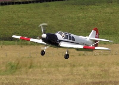
As is our custom, I took the photos, Gareth W handled the test flight, and Crash was press-ganged into a Ground Support role. Lined up on the grass strip she rolled forward, quickly gained speed and gently, and oh-so-scale-like, slipped into the air. Gareth kept her low to build up airspeed, then as height increased, he made the first turn. With the wheels retracted she looked absolutely convincing, and the sound of the Thunder Tiger was quite thrilling – every inch a private light aircraft.
All went well – loops and rolls, a stall turn… then, inexplicably, the engine cut at a low height, whereupon Gareth had to quickly side-slip her onto the strip for a neat landing. Dead-stick, she had a good glide, being not at all hairy or worrying – more lady-like and docile. We were delighted. I tweaked the engine a bit, and we tried again.
This time, power was much more reliable, with a smoother delivery, and she looked absolutely right flying the circuit. I snapped away with the Brownie, then Gareth declared he was bored flying ‘slowly’ for the snaps and wanted to try some aerobatics. Bunts, spins, Cuban eights and pretty stall turns followed, then a fabulous combined Lomcevak and tumbling manoeuvre that drew spontaneous shouts of glee from the pits. The zero-level low passes really were ultra low with the wheels up.
PRESENCE
Graupner’s Taifun really looks the part in the air, and being slightly larger than the average club model, has great ‘presence’. With the brand new .91 in tune, she pulled big loops, climbing all the way to twelve o’clock in a very scale-like manner, as opposed to the usual over-speed sports flip – more full-size than model in appearance. Gareth made all the manoeuvres seem graceful and deliberate, and achieved more by letting the model fly at a comfortable pace through each element, rather than hammering the throttle.
Frankly, I was surprised how well she performed vertically, whilst maintaining a low-ish speed. Actually, speed did not seem to vary too much between upward and downwards manoeuvres; indeed, Gareth hardly strayed above half throttle. When I had a go later, I was amazed how easy she was to fly, the hardest part being to remember that I must drop the undercarriage before landing. Applying the flaps induces only a slight nose-down trim change, although for maximum effect, you do have to tune a low tick-over from your engine – then, she’ll come in steep, and really slowly. Adding flaps at take-off is less noticeable, since she already has superb characteristics in that regard.
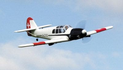
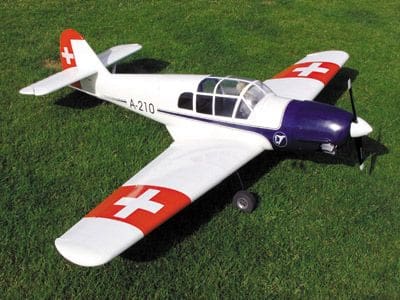
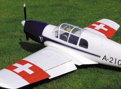
You can spend many happy hours absorbed in playing with various flap settings, and coaxing this already viceless aircraft to even better performances. As a first foray into truly ‘multiple’ controls, and to learn about retracts and flaps, she is absolutely ideal. Being a scale man, just watching her fly around wheels-up, with all that glasswork and the vivid red, white and blue livery was a joy, especially when the cockpit caught a flash of the sun.
THE VERDICT
This aircraft is an absolute gem. Viceless, flies like a trainer, and is very well matched to a Thunder Tiger .91 four-stroke. The Taifun kit is very complete, and builds simply and quickly, despite the added complexity of flaps and retracts. This model is handsome, has no shortcomings in handling, and looks very convincing. There were many compliments at the field about the pre-decorated covering, and the overall ‘presence’ of the thing. On top of all this, Me 108 Taifuns are very rare in model form.
DATAFILE
Name: Me108 Taifun
Model type: Scale
Manufacturer: Graupner
RRP: £199 approx (Jan 2012)
Wingspan: 1640mm
All-up weight: 4,800g
Control functions: rudder, elevator, aileron, throttle, flap, undercarriage
Engine range: 60 – 65 two-stroke, 91 four-stroke


