
The Ohm 8 plan is available via the RCM&E plans service. This article and pull out plan were originally published in RCM&E, May 1964. It is reproduced in its original form, including references to R/C equipment of the time but with minor modifications could be easily fitted with modern mini/micro servos and a .15 cu.in. glow engine. Or why not try electric? A materials list follows at the foot of this article.
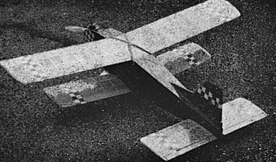
Ohm 8 was designed as a fairly stuntable but beefy and easy to fly trainer for basic multi installations, Twin Triple, Galloping Ghost and similar equipment. With Twin Triple the actuator system can be used as intended, i.e. with torque-rod rudder, push-pull elevator, and blipped engine control via a Rising clockwork or similar escapement. Ghost gear is easy to accommodate and almost any multi equipment weighing up to about 1 lb. can be fitted, which gives scope for the three basic controls – rudder, engine and elevator – on most six-channel gear. The prototype, with four channel Grundig gear using hefty dry batteries for servos, came out at 3 lb. 7 oz. total, of which 17 oz. was radio weight.
At this weight the O.S. Max 15 III fitted produced quite a rapid climb on full throttle. One of the most satisfying things about the model was the fact that it flew off the board, the only modification needed being an extra degree of downthrust to iron out a tendency to “climb stairs” at full throttle; the drawing has incorporated this minor change. Stability is just about right and it would be quite safe to use rudder only gear if a little prudence was used to feel the characteristics out on the first flight or two. Space
for equipment is no problem – the fuselage is positively voluminous – but the heavier items should be stowed low. Strength is considerable; initial flights were made with the throttle control reversed and the second flight finished up with a vertical dive in (following an open-up when a full close-down had been intended!) with no damage to speak of. In fact the model, when reassembled, was ready to fly again.
Enjoy more RCM&E Magazine reading every month.
Click here to subscribe & save.
It is very straightforward and economical to build, and despite two wings can be built quicker than many monoplanes of similar area. Transportation is easy – the biggest piece is the upper wing at 42 x 7in., despite a total surface area of nearly 600 sq. in. (approx. 14 oz. sq. ft. loading). Flying is definitely a pleasure and appearance – well it's always a question of taste – and a stubby little biplane which somehow looks right will always find its adherents.
Construction
Trace and cut the fuselage sides; if 6in. wide sheet is not available locally, butt join two 3 in. sheets. Lay on a flat surface and cement the 1⁄16in. sheet doublers in place, using balsa cement, impact glue or P.V.A. Add engine plate bearers. Cut bulkheads and assemble sides to the two large ones beneath wing, adding 1⁄4in. sq. fillet strips. When dry, draw in nose and tail and fit remaining bulkheads; note that the fuselage will bulge slightly between B2-B3, and the floor will therefore not be a plain rectangle. Place fuselage over paper and draw round wing mount part; allow for sides thickness and cut template to fit. When fit is satisfactory, use template to cut ply floor.
Fit all gussets, dowels, etc. and complete installation scheme (push-rods, wiring, etc.) before sheeting top and bottom (3⁄32in. sheet, grain across fuselage). Sheet across bearers between B1 and B2. Before closing tail end, make and fit fin – note that centre spar is gusseted into fuselage to lock fin firmly in place. Be liberal with strengthening around undercarriage plate. Cut motor mounting plate.
Tissue cover entire assembly and dope and finish in the usual way, not overlooking thorough fuel proofing inside and out at the nose end.
The rudder should be made and fitted in the fin during construction of the latter. The dowel hinges used are extremely free-moving and reliable but must be built in as work proceeds.
Wings and tail all use webbed spars – it doesn’t take long to include the webs, but the increase in rigidity, especially torsionally, is astounding. Pin down wing panel L.E., T.E. and lower spar, add dihedral brace, ribs, webs (vertical grain 1⁄16in. sheet pieces between ribs and spars), add top spar, and that’s one panel. Prop panel to correct angle to engage dihedral keeper with second panel. When complete add centre section, tip blocks and gussets, sand all over and cover with heavyweight tissue, silk or nylon. Note that one L.E. and T.E. cut carefully will do one upper and one lower panel, plus one centre section.
The tailplane spars are cut from 3⁄32in. sheet and construction is similar except for absence of dihedral and the T.E., which is 1⁄4in. sq., and of course the dowel hinges, which can be slid through the ply “eyes” and central rolled gum-paper tube before attaching the tip blocks. Take care when cementing the elevators to the dowel (after insertion, of course) that both elevators are accurately lined up.
Anyone wishing to fit ailerons can use the same system (upper wing only), i.e. use a 1⁄4in. sq. T.E., hinge shaped 3⁄4in. T.E., for ailerons, and the rest of the shaped t.e., to the 1⁄4in. sq. to form a normal T.E.
On the prototype when fitted with Twin Triple, the rudder torque rod ran through the dorsal fin (made hollow for this purpose) and out at the base of the fin proper. The push-pull elevator rod engaged a wire which ran in acetate framed slots each side of the fuselage; the wire bent back at one end to pick up the elevator horn. This obviated any twisting or binding. Two EImic escapement winders were fitted just in front of the rear bulkhead, and the throttle actuator sat just behind the tank.
For throttle, rudder with Grundig gear, a push-pull rudder rod connected a Bellamatic, bolted inside the fuselage side,
to a rudder horn, emerging from the fuselage beside the dorsal fin. A Servo-automatic was mounted behind the tank, but could have been in the main bay. The elevators were cemented lightly in neutral.
Assemble the model, strapping the undercarriage on securely in particular, and check for balance. If the balance point is as on the plan (or can be adjusted to this point) and you have built reasonably true, there is no point in test gliding and we recommend power flights from the start – not perhaps full power for the very first flight! – confident that it will perform as well for you as it did (and does) for us. Additional installation information is shown on the plan, so you should have very little difficulty in making multi servos connect up with the control surfaces and plenty of room is left for most multi receivers. Finish the model and check the C.G. while trying mockup installations in order to keep the C.G. where specified.
Materials
21⁄8" x 6" x 36" med. balsa (fus. sides)
21⁄16" x 3" x 36" med. hard (fus. side doublers)
43⁄32" x 3" x 36" med. hard (fus. top & bottom, ribs, tail spars)
11⁄16" x 3" x 36" med. (centre sheeting, spar webs, etc.)
21⁄2" x 1⁄2" x 36" pre shaped L.E. (both wings)
21⁄4" x 1" x 36" pre shaped T.E. (both wings)
13⁄8" x 3⁄8" x 36" pre shaped L.E. (tail)
13⁄16" x 3⁄4" x 36" pre shaped T.E. (elevator, wing and u/c stops)
41⁄8" x 3⁄8" x 36" hard (wing spars)
61⁄4" x 1⁄4" x 36" med. (formers, fin, tailplane t.e. etc.)
11⁄32" x 3" x 36" med. (fin sheeting)
5" 1⁄8" dowel (rudder hinge)
20" 3⁄16" dowel (elevator hinge)
30" 1⁄4" dowel (band hooks, etc.)
18" 3⁄8" x 1⁄2" engine bearer
6" x 12" x 1⁄8" ply (motor plate, bulkheads, dihedral braces)
9" x 9" x 1⁄16" ply (bulkheads, floor, gussets)
6" 14 s.w.g. wire (tailskid)
1 Veron dural undercarriage,
21⁄4" sponge wheels
Scrap 1⁄4" sheet (rudder, etc.)
Scrap 3⁄4" soft block (tips, etc.)


