
We recently looked at setting up a model and introduced the (relatively simple) positive spin into our aerobatic repertoire. There are quite a few types of spin, some harder than others – the inverted, or negative spin, is our focus this time, but first we’ll further explore the crucial area of model set-up.
We’ve talked about control surfaces, symmetry and 90° angles in control rod geometry with the assumption that the model’s been built straight and true; for an aeroplane to perform properly and consistently over different speeds it must be twist and warp-free. Ultimately the aim is to achieve straight and level flight through correct symmetry, incidence, balance and thrust line… assuming that the design is basically sound, of course! Trim adjustments, trim tabs and mixing are all second best ‘fixes’ that should be avoided.
So often I’ve seen a good design prove to be very capable in the hands of one builder / flyer, yet turn out distinctly average with another. Given that the design is a good one, such disparity can only be down to one of two things: a fault in either the kit or the build. Responsibility ultimately comes down to the builder; a careful or experienced modeller should hopefully spot any problem in the kit and take corrective action before it’s flown.
EQUAL OPPORTUNITY
Last time out we covered the fundamentals of basic balance, looking at the C of G and the addition of tip weight to achieve lateral balance. Next on the list is symmetry so let’s take a closer look at this, beginning with the wings.
Enjoy more RCM&E Magazine reading every month.
Click here to subscribe & save.
Say, for example, that your aerobatic or sports model has wood-skinned foam wings, as is often the case. Don’t assume they’re perfect… of course they should be, but it’s not always so. I’ve seen such imperfection in top class models as well as those at the cheaper end of the spectrum and in all likelihood it’s just a glitch in manufacture or quality control – either way, the consumer expects perfection! So, what are the symptoms of imperfection we’re talking about? Well, basically, it’s warp or twist of the wing panels.
Some models do require twist however, in the form of wash-out or wash-in (where the t.e. at the wing tips is angled slightly up or down). Aerobatic designs don’t require this and should have perfectly straight wing panels. If you don’t have a pair of commercially available incidence meters, there is an easy way to check for unwanted twist. Before joining the wing panels, carefully mark a line from the centre of the l.e. to the centre of the t.e. at each tip, then pin / tape some accurately cut parallel strips of balsa against this line (see above). The (identical) height of these jig strips isn’t too critical, unless you plan to use this method to set the dihedral, but they need to be of sufficient size to lift the tip section off the bench. The main aim at this time is to ensure that the wing tips of both panels are parallel with each other.
Offer the roots of each panel together, ensuring that the panels haven’t twisted and that the balsa jigs at the tips are properly in place and touching the bench all the way along. Provided your bench is straight and true and the roots of each panel match up nicely, you’re blessed with straight and true panels. If the leading and trailing edges don’t match at the centre then one panel (or both) might be twisted.
You can get away with a small amount of twist, indeed 1/8” difference between the panels at the root t.e. is just about acceptable. In this case when it comes to gluing the panels together you must aim to keep the tips true and take up the twist at the centre. Beyond 1/8” becomes arguably unacceptable and you should repeat the tip alignment test at the root on each panel in turn to determine which one has the twist. As a last resort, consider returning the panel to the manufacturer for replacement.
This might seem a bit drastic, but if you’re looking for a pleasant and accurate machine to fly then you’re cheating yourself to go through the remainder of the build with what will never be an accurate model. Besides, if you paid good money for straight panels then that’s what you should receive!
Next month we’ll take a look at other aspects of model symmetry and how to achieve it in the build, meanwhile let’s put another manoeuvre under the spotlight.
NEGATIVE SPIN
Over the next couple of months I thought we’d take a look at a selection of manoeuvres that are derived from the spin. Let’s pump up the gas and examine the negative version.
Pilots are sometimes frightened to put their model into a spin early on as it feels like it’s out of control, i.e. you can’t really see what’s happening. Keep practicing and the spin will appear to become slower, whereupon you’ll keep up with it and discover that you can stop it just when and where you want. The rate of spin isn’t changing, you’re just getting accustomed to following it. Assuming you’re comfortable with holding the sticks in the bottom left or bottom right corners for the positive spin, let’s throw everything on its head and go negative, otherwise known as the inverted spin.
To start off we’ll approach the manoeuvre in a similar way to the positive spin, but it will be more difficult to achieve. Last month we talked about approaching the spin straight and level, dropping the power to idle and steering the model in a straight line up to the point of stall, when a little rudder may then be used to influence the direction of the manoeuvre. Try doing that upside-down and you might find it goes a bit wrong the first time. However, don’t worry, keep practicing and remember we’re aiming for an identical pattern of entry to the positive spin with an emphasis on using that rudder to steer the model.
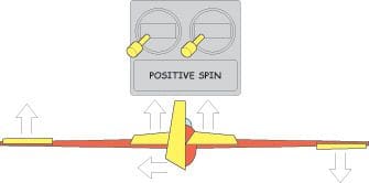
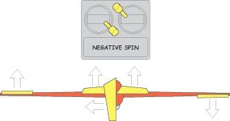
Just like the positive version, you may wish or need to influence the direction in which the aircraft will stall. This being the case, begin the spin with the use of a little rudder at the point the model stops moving forward. This time though (assuming we’re flying Mode 2), you’re not going to push the right stick into the same corner as the left – i.e. full aileron movement in the same direction as the rudder coupled with full up elevator / low throttle – Fig. 2. Instead, you’ll use opposing rudder and aileron inputs and down elevator, i.e. whatever mode you fly, both sticks will be pointing into the middle of the Tx or to the outside – one will be in the bottom corner of the gimbal (throttle stick) and the other in the opposite top corner – Fig. 3.
Make sense? Models that aren’t fully symmetrical pattern ships can often spin more rapidly or violently inverted than upright, so don’t panic if you feel like you’re back at square one and everything is a blur, just make sure to start from a safe height. Keep practicing and the entry will improve; you’ll soon become used to the model’s behaviour in a negative spin and be able to stop it precisely where you wish, in order to make a controlled vertical descent and pull out at the bottom.
If the manoeuvre feels too violent still, then reducing the amount of aileron or elevator input (or sometimes both) will help slow it down. Do this by feel to start with to see which makes the most stable impact and then either reduce the control input or set the rates on your Tx… and remember, you’re spinning with the engine at idle!


