I spent two fantastic months during 2004 touring New Zealand – a country that boasts wonderful scenery and is an aeromodellers dream, with innumerable potential flying fields and slope soaring sites. As an avid modeller for the past 50 years I felt it my duty to seek out fellow soul mates, and whilst in Blenheim on South Island I made contact with the local fliers and enjoyed a couple of sessions with them (purely as a spectator, as they all fly mode 1 and I fly mode 2).
During these sessions I met a Kiwi named Guy Marfell; we promised to stay in touch, exchanging email addresses, and I said that if I ever visited again I would bring a model of my own to fly. We did indeed stay in touch, and I made plans for a return visit the following year. Remembering my promise about taking a model I set about deciding what it should be, bearing in mind that transporting a large i.c.-powered design would pose a considerable number of logistical (and possibly security) problems.
After giving it some thought an electric powered something seemed to offer the best possibility, it would need to be of a reasonable size and have a performance to justify taking it the 12,000 miles! Eventually I decided that a 36″ (914mm) span fun flier powered by one of the latest outrunner brushless motors would fit the bill. I couldn’t find an ‘off the shelf’ airframe suitable so I set about drawing up some plans of my own. The final result was a model based on a typical fun fly (Limbo Dancer / Frantic), powered by an AXI 2808/24 brushless motor.
Full of enthusiasm, I acquired the necessary components and started building. The model took about four weeks to complete and came out very much as planned, weighing 24oz (680g) to give a power rating with the AXI motor of around 80W per lb (0.4kg). I reckoned that this, coupled with a wing loading of 10oz / sq. ft., would give a good performance.
Article continues below…
Enjoy more RCM&E Magazine reading every month.
Click here to subscribe & save.
 TRANSPORT TATTLE
At this point I thought it would be a good idea to talk to the nice man at Singapore Airlines about the transportation of the model and associated gear (Tx, batteries, charging equipment etc.) Fearing that putting the model in an unpressurised baggage compartment might cause structural damage, I asked if it could be taken as cabin baggage. Much to my surprise he said that this would be possible, providing precautions were taken to immobilise the Tx. I subsequently made a 39 x 12 x 6 ply box, which I was assured by Singapore Airlines would be accommodated in the overhead locker of a Boeing 747.
With the model finished and everything else ready, I was undecided as to whether a test flight should be made prior to departure. I eventually decided against this; having got so far the thought of damaging it at this late stage would have proved very disappointing. I set off in late January 2005 with the, as yet unnamed, model stowed (much to my relief) as planned in the overhead locker. Singapore Airlines, and in particular their cabin staff, were extremely helpful and at times put themselves out on my behalf. The model can justly claim to be one of the few electric aircraft to make a first flight of just over 12 hours (i.e. the first leg to NZ via Singapore!).
KIWI SKIES
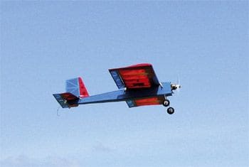
Five days later, after a stopover in Singapore and driving up from Christchurch, I arrived in Blenheim where I met up with Guy and made plans to go out to the Woodbourne (Blenheim) club field. On arrival the model was soon assembled and preparations made for its first flight under its own steam. Fortunately the weather conditions were absolutely perfect, so without further ado I eased the throttle stick forward; away she went, lifting off after about 10 (3m) and climbing smoothly into the New Zealand sunshine.
Apart from a few clicks of aileron and a little down trim, all was fine. The effect was a big sigh of relief on my part as I felt I had something to prove to my NZ friends about us poms! Fortunately the model exceeded all my hopes by a fair margin, proving very aerobatic and easy to fly just like its bigger, i.c.-powered brothers. The combination of AXI 2808/24 motor on a 9.6V 1050mAh NiMH and Graupner 9 x 4 Slimprop gives a static thrust of around 24oz (680g), which equates to a thrust-to-weight ratio of 1:1.
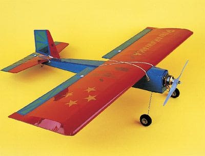
Now it had proven itself, I reckoned it was time this anonymous aircraft was given a name, something appropriate that reflected its link with New Zealand. Comments were made that seeing the model darting about the NZ sky was akin to the performance of an indigenous bird of NZ called the Fantail. I was really looking for a Maori name and was told the Fantail was known in Maori as Piwakawaka; sounded good to me, so Piwakawaka it was. (Piwakawaka: A cheeky restless bird instantly recognisable by its erratic flitting flight – as it hunts its insect prey while on the wing – and by its attractive spreading tail).
ELECTRIC AMBASSADOR
During my 6-week stay in Blenheim, Piwakawaka (or Pi as she is now affectionately called) was flown many times, in superb flying conditions that we poor British modellers can only dream of! The performance of the model (and particularly its brushless motor) surprised and intrigued the local fliers and may well influence them to consider trying this branch of our wonderful hobby in the near future.
In the end the idea of taking a model to the other side of the world, which at the outset sounded a little crazy, turned out to be a resounding success. Having completed her world tour Pi returned to the UK skies, and it was whilst wringing her out one day that I wondered whether RCM&E readers might like to share her. A quick word with ed. Graham, and the deal was struck. So, if you like the look of Pi and fancy building your own version, then heres how to go about it.
WING
Start by cutting out the wing ribs W1 from 1/8balsa sheet and W2 / W3 from 1/16. Ribs W3 have notches for the 1/2 x 1/8 liteply servo mounts and holes for the servo leads. Shape the 1/4 x 1/2 medium balsa t.e., tapering it down to 1/8 to match the aileron thickness.
Pin down the bottom 1/4 x 1/8 main spar and t.e. then fit the ribs, packing them up at the underside of the t.e. with scrap 1/32 to allow for capping strips. Add the top 1/4 x 1/8 main spar and the false 5/8 x 1/8 medium balsa l.e. Fit triangular 1/8 balsa fillets where the ribs meet the t.e., to give additional support. Whilst the wings still pinned to the board, carefully sand the top of the l.e. to follow the contour of the ribs and fit the 1/32 l.e. sheeting back to the main spars. Continue by adding the 1/32centre-section sheet and rib cap strips.
When dry, remove the wing from the board and carefully shape the underside of the l.e. before fitting the lower l.e. sheeting, centre-section sheeting and cap strips. Okay so far? Great! Trim the l.e. sheeting and then add the final 1/8 balsa sheet l.e. Fit 1/8 balsa sheet wing tips and balsa fillets, then sand the wing tips and l.e. to conform to the wing section.
Don’t forget to add cap strips over the servo mount supports, as these will be needed when covering the wing. Cut two 1/32 ply servo mounts to fit apertures in the wing; small screws can be used to retain these, to make servo fitting and removal easy. A hole will need to be cut in the underside of the centre-section sheeting to allow the servo leads to pass through.
FUSELAGE
Cut out two fuselage sides from medium 3/32 balsa, noting that the front incorporates a small amount of down-thrust on former F1. Add 1/8 square fillets to what will be the corners of the fuselage at the bottom and from the wing trailing edge position to the tailplane mount.
Next, fit the 3/16 balsa wing saddle W11 and the triangular, 1/8 balsa wing dowel doublers. It’s probably worth marking the position of the formers on the two sides at this point. Whilst the fuselage sides are drying cut formers F1 from 1/8 liteply, F2 from 1/8balsa, F6 from 1/4 balsa and F7 from a small balsa block. Former F3 is made from 3/8 x 1/8 balsa as shown on the plan.
Join the fuselage sides together using F1 and F3, ensuring everything remains square. When the glues dry, pull the sides together at the rear and join using F6 and F7. Add 1/4 triangular fillets to the bottom and sides of F1 in order to provide extra support. Fit the 1/8 ply undercarriage mount F4 to the bottom of the fuselage as shown and add further 1/8 balsa (cross grain) back to F3. Beyond here the remainder of sheeting is 1/16 balsa (cross grain); also from the trailing edge of the wing to F9.
Drill two holes in F4 for the undercarriage wire to pass through, into the inside edge of the fuselage side. Note that the holes need to be displaced by one hole diameter in order to allow the u/c wires to lay alongside one another (for clarification see the underside drawing of the u/c fitting).
Form the 14swg wire u/c legs as shown on the plan, slot into position, then fit the two liteply reinforcing plates on the inner fuselage sides to fit snugly against the wire. Add the 1/16 ply u/c strips F5, spaced to accommodate the two u/c legs. Holes for the wing retaining dowels can now be drilled through the fuselage as shown on the plan.
Formers F2, along with the speed controller tray and battery stop are shown in their nominal positions but you may want to adjust them to suit you own particular installation. Ensure that the wing and tailplane mountings are square to the fuselage and parallel to one another, then add the 3/32 sheet tailplane mount F8. Note that this extends forward to provide support to the base of the fin.
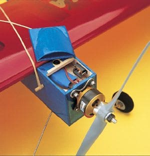
Fit F10 (1/4 x 1/2 balsa) just ahead of the wing to provide a base for the fuselage top, this made from 1/8 balsa with a hole for providing cooling air to the speed controller. Here, an air scoop is made by bending a piece of dampened 1/16 balsa around a suitable 2 diameter former, shaped as shown on the plan. This top hatch was retained on the prototype using a press-stud at the rear and a small tongue at the front. Ideal for easy access to the speed controller and fixing screws of the drive motor.
Article continues below…
 Since the basic fuselage is now complete, the corners can be rounded as shown in the cross-section (see plan) and the remainder given a general sanding.
TAIL FEATHERS
Cut the tailplane from 1/8 light balsa and fit 3/8 x 1/8 anti-warp strips to the tips; this is important to ensure everything remains true after covering. If the tailplane is to be made removable (as on the prototype), cut a semi-circular hole in centre of the t.e. to allow the elastic band fixing to pass through. Cut lightening holes in the tailplane if desired, though these are probably unnecessary as the C of G should come out fine without them. The fin is made from 1/8 light balsa and extends below the top of the fuselage to contact F8, the tailplane support.
All control surfaces are constructed from various sizes of 1/8 medium balsa strip. A plug here for the SLEC balsa stripper – its an absolute must have for any builder. With this its a cinch to cut the requisite widths of wood from those odd scraps of sheet you have left over from your last project! Take care to make good, accurate joints, as this will ensure that everything stays true after covering.
FINISHING
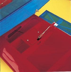
After a final sanding of all the parts make a careful inspection and de-dust everything prior to covering. The prototype was wrapped in translucent Solarfilm, which provides a durable and lightweight finish. In order to make Pi more transportable, the tailplane was made removable and held on by elastic bands (as described above); if you go for the fixed option then glue it in position, having carefully removed the covering film on the underside where it glues to the tailplane mount. The fin is then fitted through a slot cut in the top of the fuselage and pushed down to contact F8. Make sure to fit the two 1/8 fillets either side to give additional support.
The undercarriage legs are retained by two small saddle clamps as shown on the plan, the lightweight 13/4 foam wheels secured with collets.
Article continues below…
 RADIO INSTALLATION
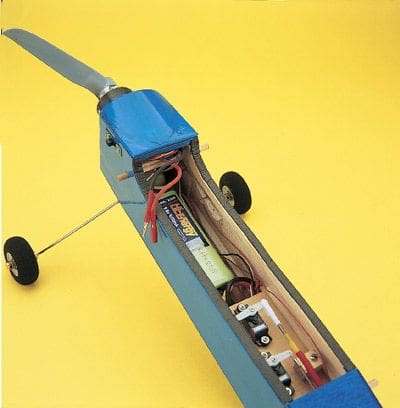
The motor is best fitted using a purpose-designed radial mount directly onto F1, although other methods and motor types should be easily accommodated. Servo installation is dependant on the radio gear you intend to use; the space available isn’t too restricted but does require the use of micro gear (e.g. 1.2 kg / cm torque servos, such as Futaba S3106, Hitec HS55 etc.) and a 5-channel Rx such as a Jeti Micro 5.
When it comes to the rudder linkage this is best made with a closed loop system using fishing trace or nylon line; a home-spun rudder horn from 1/16 liteply was used for the prototype. The elevator linkage, on the other hand, uses a snake, though a pushrod from stiff 3/16 balsa would do just as well.
The ailerons use separate servos, which gives far better control response and enables them to be used as flaps or in coupled aileron / elevator mode if required. These particular servos are fitted to the 1/32 ply servo mounts using either servo mounting tape or small hardwood blocks. The leads from the servos pass through the ribs and exit through the lower centre-section sheeting.
FLYING
Double check that the C of G is in the right place and that the controls operate in the correct direction. As mentioned above, Pi is very aerobatic and capable of just about every manoeuvre except perhaps knife-edge – but maybe that’s down to my deficient piloting skills! Built light, with a power-to-weight ratio of close to 1:1 and the right propeller combination, it may even be capable of prop hanging!
Pi will ROG from most well-mown grass strips, but if your patch isn’t particularly suitable in this respect then initial trimming flights can be made from a hand-launch; thereafter a single-handed under arm lob should see her safely away. The performance with the AXI 2808/24 is more than adequate and shell loop from level flight on about 3/4 throttle, so no doubt lower power combinations of around 80W would give adequate performance.
 As with all fun-fly type models it’s possible to take the most outrageous liberties with Pi, without her biting back. You’ll be pleased to know that the stall is virtually non-existent, full up elevator causing nothing more than a disinterested wandering, and she can be flown in quite breezy conditions (she’s certainly no strict fair weather maiden). Small, light, extremely agile and forgiving, Pi is great fun when flying quiet, close-in aeros!
As a model that can be stowed in the car and flown on an opportunistic basis, this couldn’t be better. I hope you enjoy Pi – I’m sure you won’t be disappointed!
DATAFILE
Name: Piwakawaka
Model type: Electric fun-fly
Designed by: Ray Huntley
Wingspan: 36” (914mm)
Wing area: 2.4sq. ft. (0.22sq.m.)
All-up weight: 24oz (680g)
Wing loading: 10oz / sq. ft. (3kg / sq.m.)
C of G: 3” (75mm) from wing l.e.
Motor: AXI 2808/24
Battery: 8-cell 1050 NiMH
Article continues below…
Control functions: Aileron, elevator, rudder, throttle
Control deflections
Low rate High rate Exponential
Aileron: 8mm 12mm -35%
Elevator: 10mm 15mm -25%
Rudder: 30mm 50mm -25%