After a short run of diesel-powered models in his column, Tim Hooper heads back to other forms of propulsion
Words & photos > Tim Hooper
Without further ado, here’s a pair of tiddlers for this episode. One has a twangy elastic band and the other has a super capacitor. How fashionably diverse we are!
Enjoy more RCM&E Magazine reading every month.
Click here to subscribe & save.
VMC CORSAIR
Given the success of my initial foray into rubber-powered tomfoolery with the re-issued Keil Kraft Gipsy last summer, I thought I’d have a bash at something a little smaller and more fiddly.
The Vintage Model Company was founded in 2012 and besides producing many existing designs their designer, Andrew Darby, has been hard at work producing new designs and models as well.
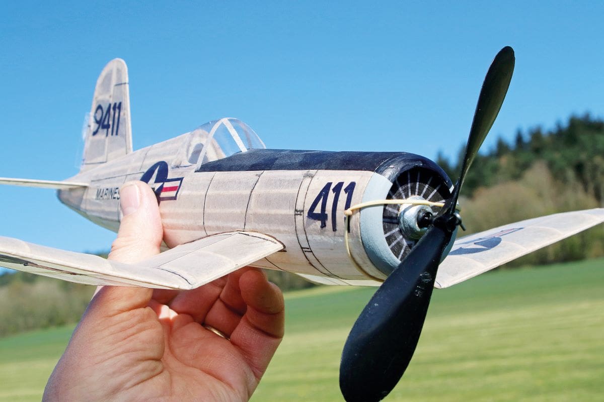
After browsing both their comprehensive website – https://www.vintagemodelcompany.com/ – as well as watching several of their construction videos on YouTube, I decided to plump for an 18” rendition of one of my favourite aeroplanes, the F4U Corsair. An inverted gull wing and a simpler…?
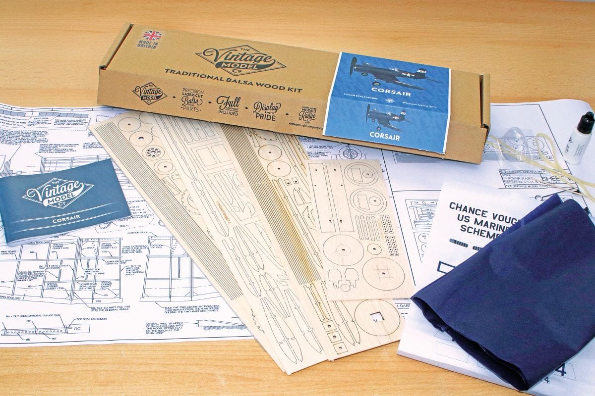
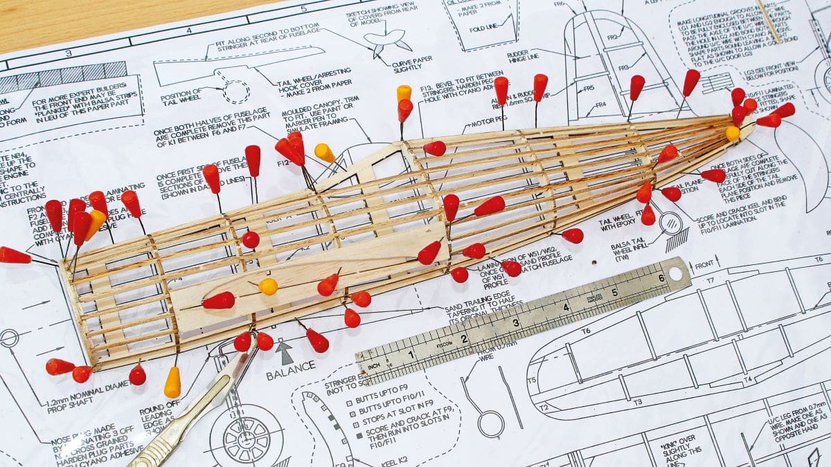
The kit arrived, purchased from Leeds Model Centre, and was a real eye-opener in terms of content, presentation and quality.
You get a rolled plan to work on, and there are several graded sheets of laser cut balsa, a very detailed instruction manual, a sheet of navy blue tissue paper, printed USN insignia, a bottle of sandable glue, a 6” propeller and rubber strip motor. Actually, the list goes on, and all for less than £30!
around 8” long and you’ll see just how detailed it is.
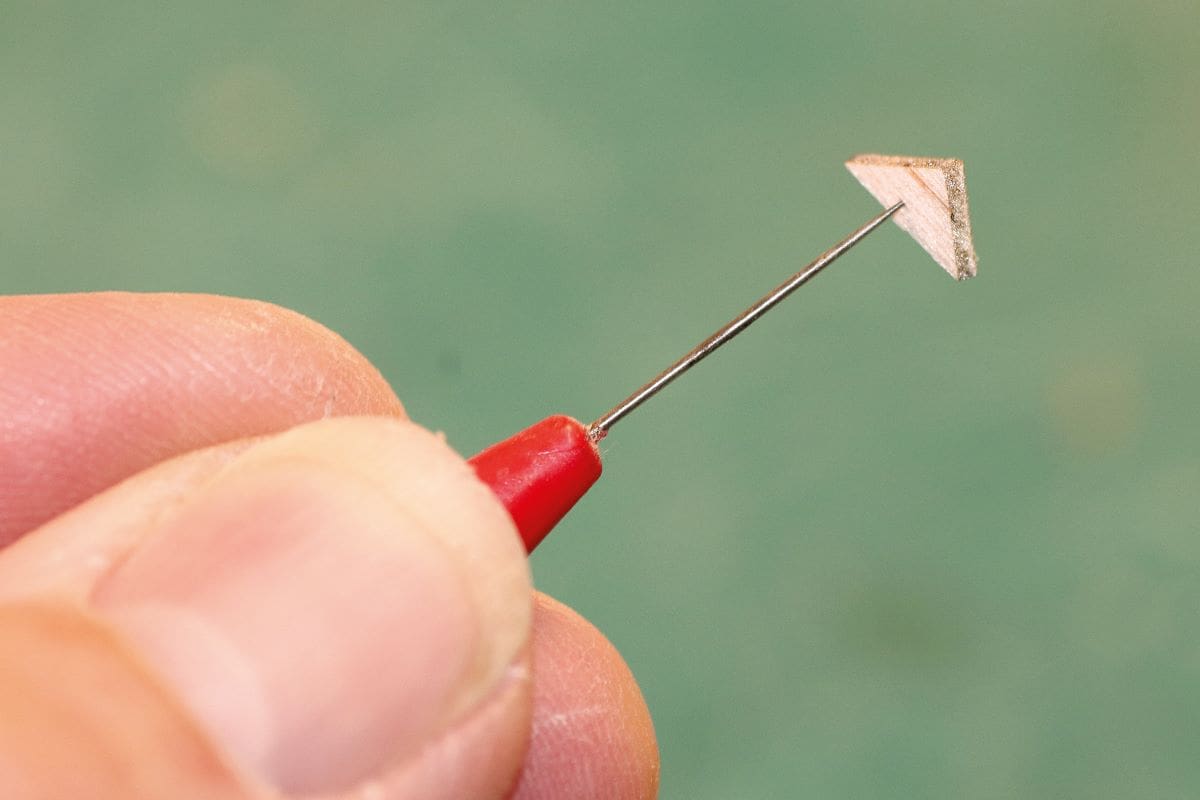
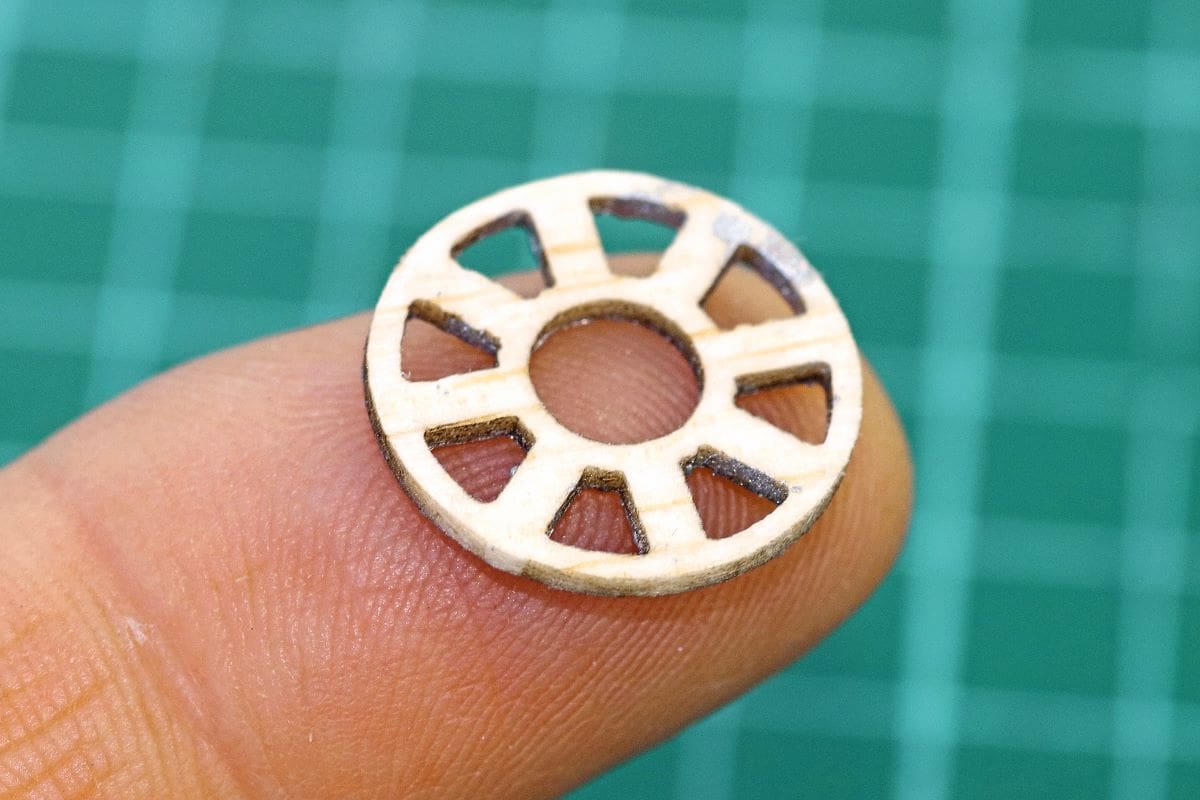
This kit takes laser cut balsa to a level I’d not encountered before. Just to illustrate; the optional wheels are based on several balsa discs, which are glued together and sanded to section. Included are two dummy, balsa hubs, which each feature the eight chubby spoked cut outs that were so distinctive on the real Corsair. Given that these hubs are a mere 20mm in diameter shows us just how high the bar has been set.
Despite its lack of size, this little Corsair is not going to take kindly to being thrown together during a rainy afternoon but is a complex piece of balsa engineering that warrants appropriate care and attention in its assembly.
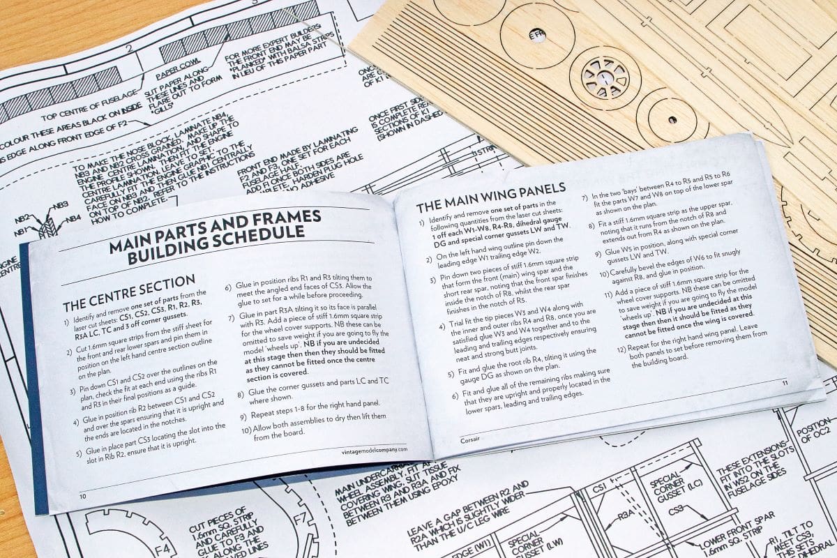
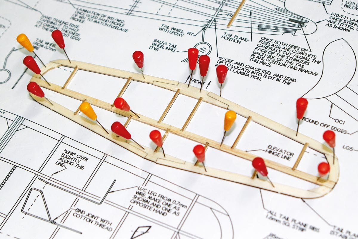
The tail surfaces are deceptively simple to build – just a few sticks pinned to the board – but that belies the sophistication of their design. All of the parts are notched and shaped to receive their neighbours. The central through-spar comes from a firm sheet of balsa, whilst the remaining outlines hail from a softer sheet. The attention to detail really is that good.
The 1/16” x 1/16” strip wood in the kit isn’t just a bundle of sticks for the builder to sort through and grade with a dirty fingernail.
Rather, there’s a section in two of the parts sheets (one firm, one softer) where the strip is lasered out and the instructions guide you on which grade of strip to use in particular locations.
GULL WING
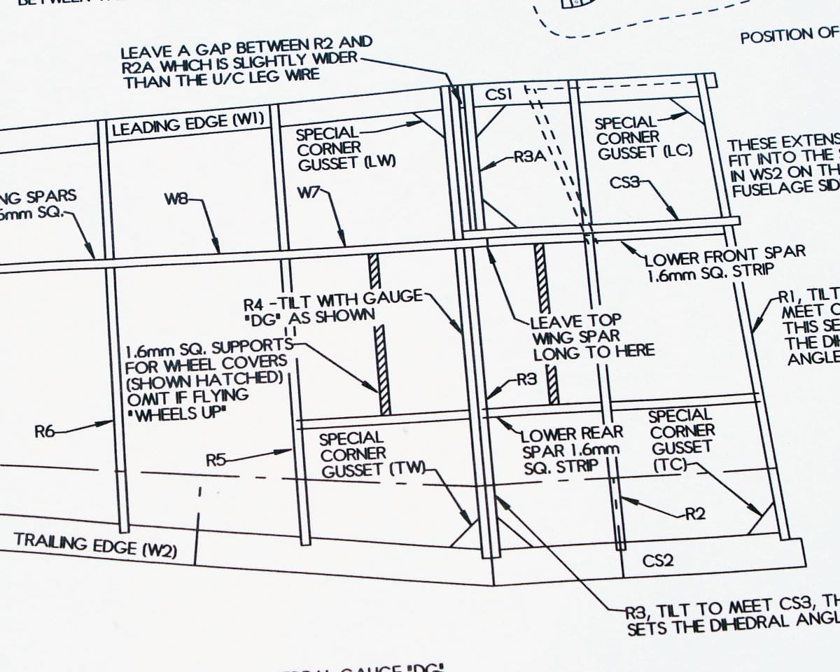
The distinctive gulled wings are built as four separate panels, with the inner panels being assembled over the plan first. Obviously, the inner ribs are angled to suit their eventual union with the sides of the fuselage using the supplied angle gauges. In time honoured fashion balsa gussets need to be fitted inside the framework to reinforce the corner joints.
Not all of these corners are at 90° so the kit has special gussets to suit the actual angles. These are all marked up on the plans.
The outer panels are similar in construction to the inners. A little point to relish here; the supplied between-spars webbing is perforated with tiny lightening holes. This can’t save more than a tiny fraction of a gramme, but it does look very professional indeed.
At this point the individual builder can decide whether to fit the undercarriage parts to his model. I decided not to, in the interests of flying performance. So, I omitted the support strips that the U/C doors can hang on later.
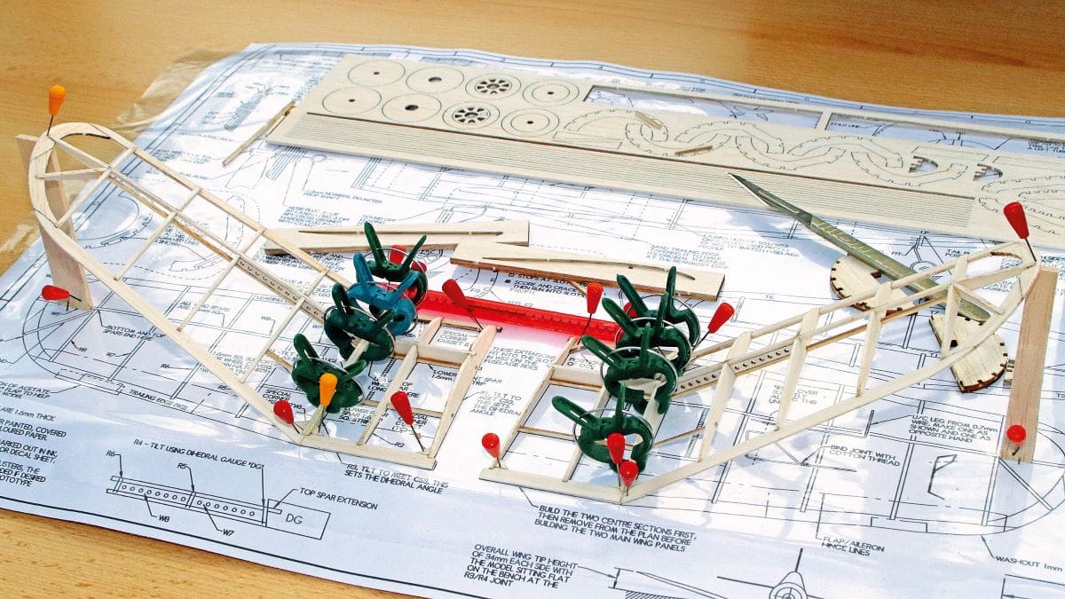
The inner panels are pinned to the board again and then the outer panels are glued in place. There looks to be an alarming amount of dihedral as a result, but don’t forget that the inner panels will be angled downwards when they’re attached to the fuselage later.
FUSELAGE NEXT
The fuselage came next in my agenda and, again, deserves time spent studying the plans and instructions before anything is actually glued together.
First piece to hit the board is the central, single piece keel. On top of this are added the half-formers that will give the fuselage its distinctive round cross section.
There’s a pre-cut side keel to add, followed by the laminated wing seats. After this the skinny stringers are added to the slots in the half formers, using the plans and manual to select each one’s grade and location. This is all painstaking work, but very rewarding in its execution. The supplied bottle of glue has a fine nozzle, which is a definite boon here.
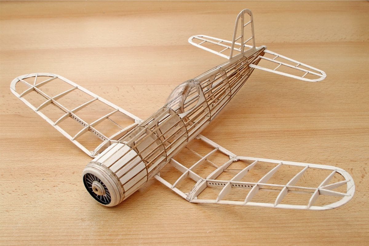
Once dry the fuselage half shell can be freed from the board and the other half formers added, followed by their own stringers. To reinforce the nose the manual suggests either an external wrap of ordinary paper or balsa infill between the stringers. Smugly, I opted to cut the twenty infill pieces of balsa, bevelling the sides of each to ensure a snug fit between the stringers.
The front of the radial cowl doubles as the removable nose block and, once again, is laminated from balsa sheet parts. Included in the markings sheet is a print of a dummy engine, which is glued in place within the cowl before the whole assembly is shaped. Using a 3mm bolt as a mandrel, I mounted the assembly in my electric drill, spun it up and used a scrap of glass paper to shape it to section.
TISSUE TIME
With the balsa work pretty much sorted it was time to break out the tissue and dope.
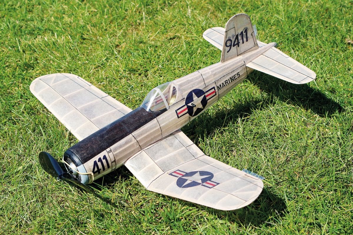
I’d long since decided to forego the supplied navy blue scheme, in favour of the later grey and white scheme that was adopted by the US Marines in the Corsair’s later service.
Using a glue stick as the initial adhesive, the wings and tail were covered in grey and white tissue before being lightly sprayed with water to shrink the tissue. The trick is to pin down the panels to little balsa blocks on the board, which will prevent the panels from warping as the water dries off.
Given the Corsair’s tapered wings, the instructions suggest building in 1mm of wash out in the outer panels during the covering operation. I’m not one to argue, so that’s what I did by raising the trailing edges at the tips. I then applied a single coat of 50/50 dope and thinners to the flying surfaces and pinned them back to the board to cure overnight.
The fuselage needs to be covered in lengthwise strips of tissue to cope with its shape and, again, it received a single coat of thinned dope afterwards. The nose block was doped, sanded and painted. The little canopy moulding was trimmed to size and fitted using canopy glue. The next day I applied a little bit of canopy framing with doped on strips of tissue.
MAIN ASSEMBLY
Now was the time to assemble the Corsair’s main components together. The wings don’t pass through the fuselage at all, but are butted to the sides in pre-shaped recesses – a technique that caused my greying eyebrows to rise a little…
I found it made sense to make up a simple foam cradle to hold the roly-poly fuselage still and then used weights, wedges and magnets to hold the wings at the correct dihedral whilst the glue dried overnight.
The tailplane slides through a slot between the stringers in the rear fuselage and received a couple of drops of glue to hold it in situ. Perhaps one of my few criticisms of the kit is the expectation to glue the fin directly to the top edge of the fuselage’s central keel, so I added a couple of locating dowels from very thin piano wire, before using a fillet of CA on each side of the join.
STARS & BARS
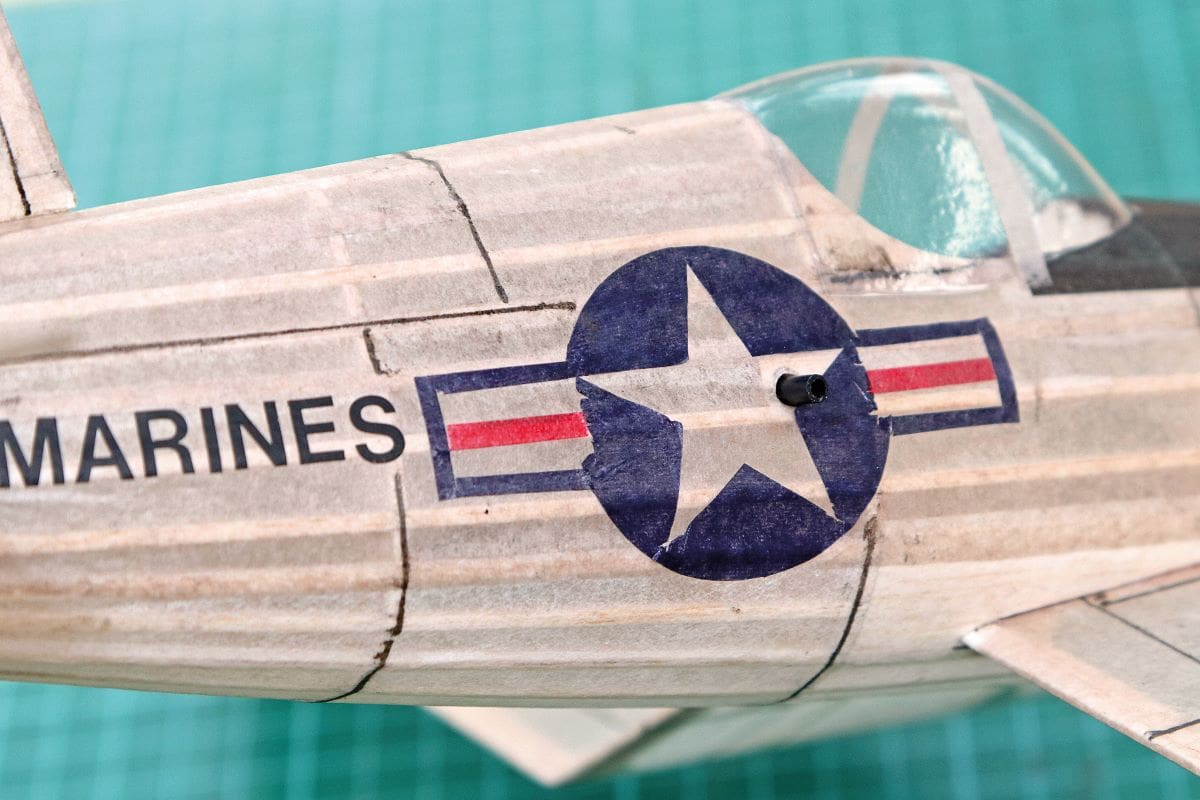
Having decided not to use the supplied paper markings the challenge now was to replicate the stars ‘n’ bars insignia. A piece of dark blue tissue was smoothed onto the sticky backing mat that comes with the Cricut cutting machine. A suitable design was found on the internet and downloaded to the machine, which was let loose on the tissue and left to its own devices for a while.
To be fair the Cricut made a decent job of the actual cutting job, despite its diminutive size and complexity. The problems arose when I tried to peel off the insignia from the sticky mat. As the pieces came free, they just curled into tight little spiral balls of paper and it took all of my patience to straighten them out, ready for doping onto the Corsair. The red, central stripes were knifed out by hand and doped in place.
The Cricut machine also coped with the registration numbers on the cowl and fin, but it drew the line at the MARINES lettering on the sides of the fuselage. I was forced to dig out my decades old box of Letraset fonts. Applying rub-on lettering to an open frame, tissue covered structure is always going to be a fine balance of using just enough pressure to release the lettering from its carrier sheet, yet not pushing through the tissue itself. I used the rounded end of a small paint brush handle and got away with it.
The panel lines were courtesy of a fine Sharpie, again taking care not to puncture the covering. The supplied cocktail stick rear peg was ousted in favour of a piece of 3mm carbon tube, which would allow the temporary fitment of a retaining rod when the Corsair was placed in the mini stooge for winding.
Then along came another lockdown and field closure, so the completed Corsair was put on a shelf in the lounge to await it’s turn for possible glory. Or ignominy. Or something in between.
To be continued…
SUPERCAP
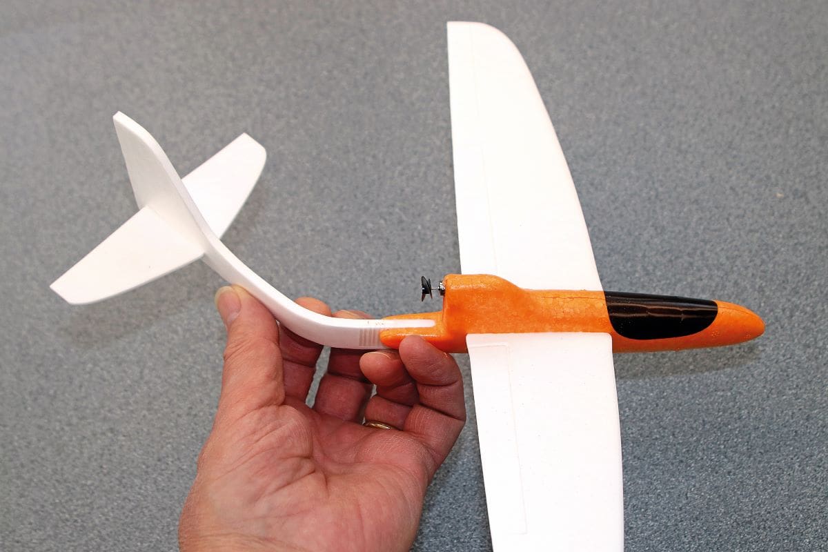
You might recall, a few episodes ago, that I was waxing ecstatic over the build and performance of the tiny, 14” span, capacitor powered Speedster, produced by the Dutch company WSAT (Wooden Shoe Aviation Toys).
Well, at the same time that I ordered the Speedster kit I also hit the ‘buy’ button on a similarly sized and powered foamie from eBay, for less than a tenner. My rationale was that even if the model didn’t fly too well then, I’d still have the innards to play around with at my leisure, wouldn’t I?
Actually, the little foamie wanted to fly – honest! But, and this seemed a fairly insurmountable ‘but’, its inherent foam construction defeated it. You see, the model was so flexible that it was impossible to flight trim it properly. Any adjustments made to the tail surfaces simply undid themselves in less than a minute and the ridiculously flexible tail boom just added to the mayhem. So, moving forwards a few weeks, to an idle, wet and windy Sunday afternoon, the idea dawned to remake the design, but in balsa, and see if it made any difference at all.
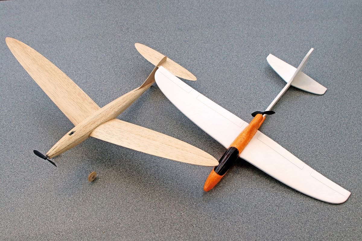
BALSA BUILD
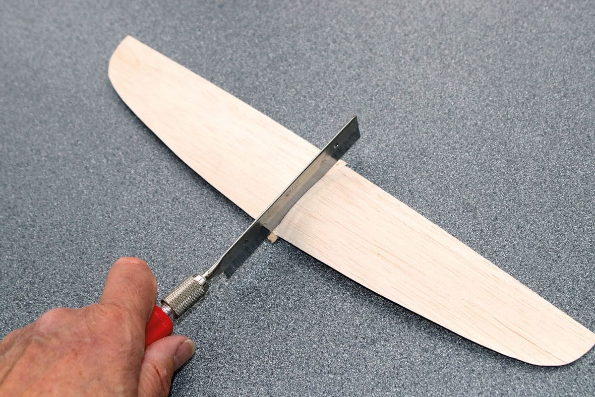
The first step was to draw around the foam flying surfaces directly onto a sheet of 1/32” balsa. Once knifed free the new wings and tail were sanded smooth and treated to a single coat of thinned non-shrinking dope on both sides, prior to another fine sanding.
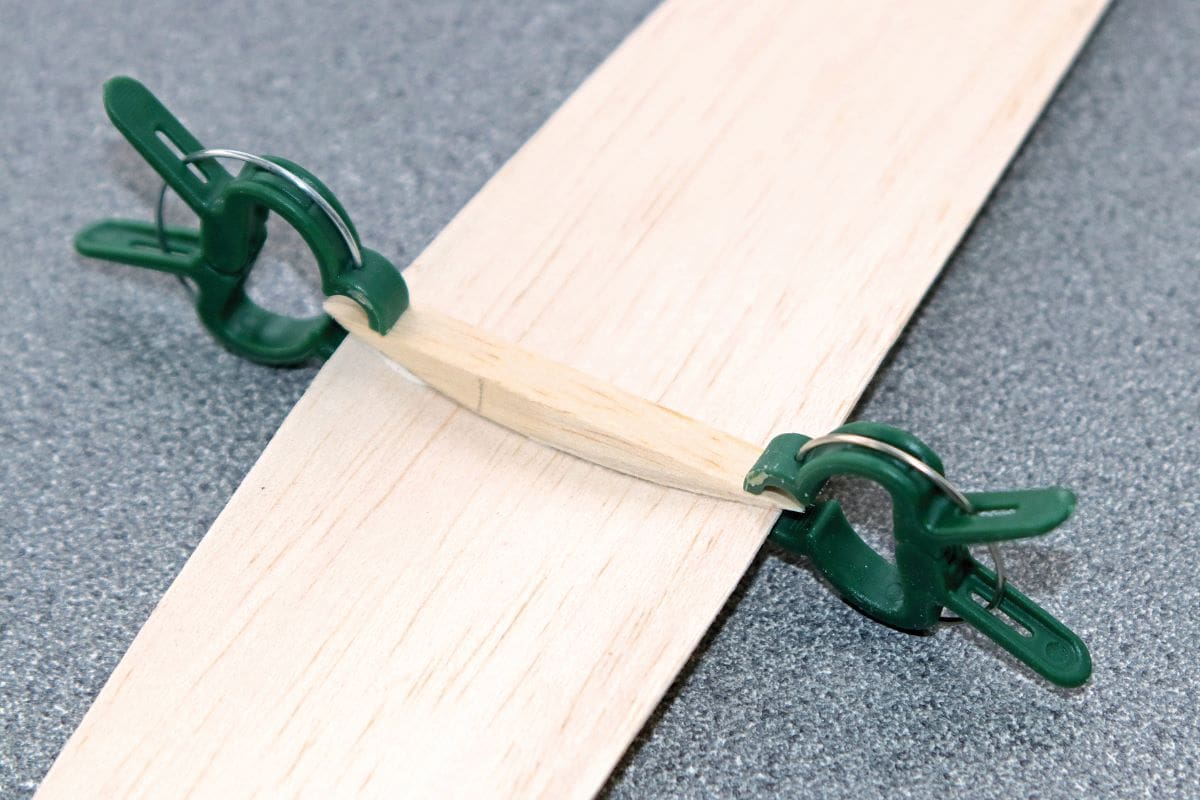
A single wing rib was drawn and cut from 1/4” balsa. This was glued below the wing’s centreline, forcing the wing into a curvature at the root. This not only gives a workable aerofoil, but also adds considerably to the rigidity of the wing as a whole. The wing was razor-sawn in half and the roots sanded to give a degree of dihedral, before gluing the panels back together again.
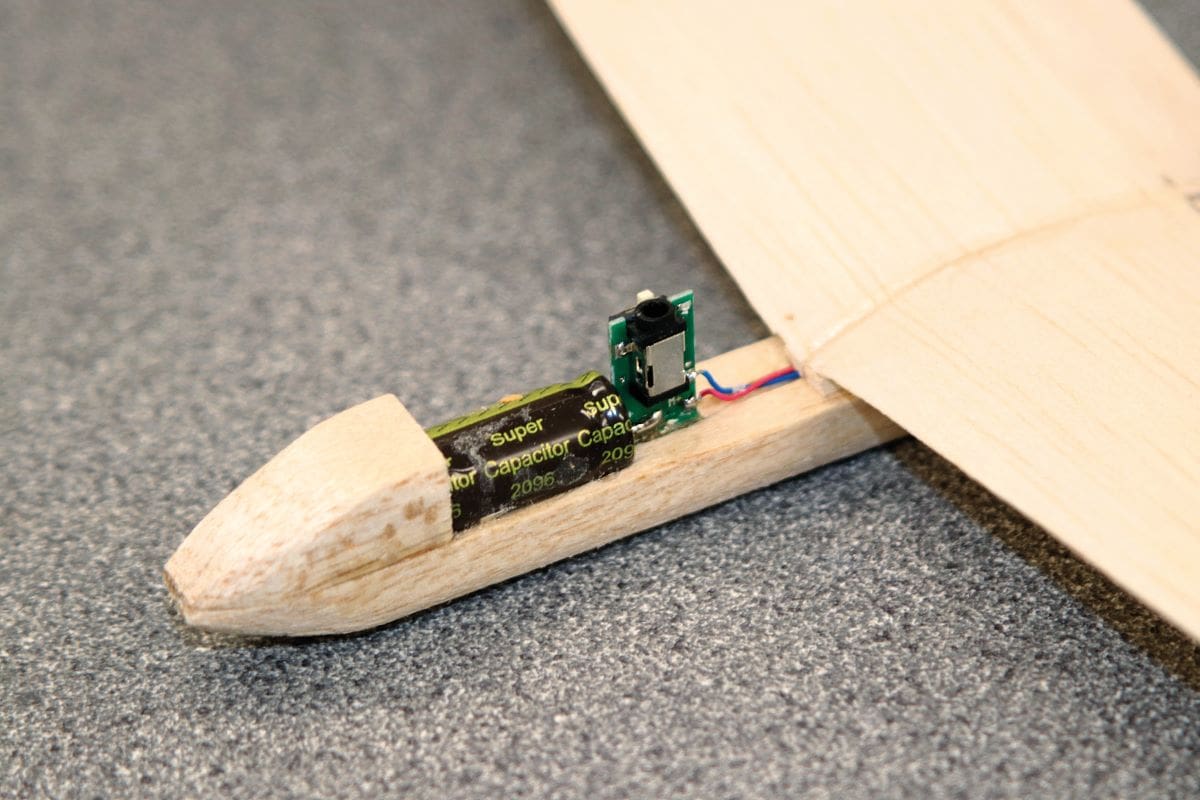
With the wings drying, I attacked the foamie’s fuselage with a scalpel and liberated the enclosed power train, consisting of the capacitor, the charging socket and the motor itself.
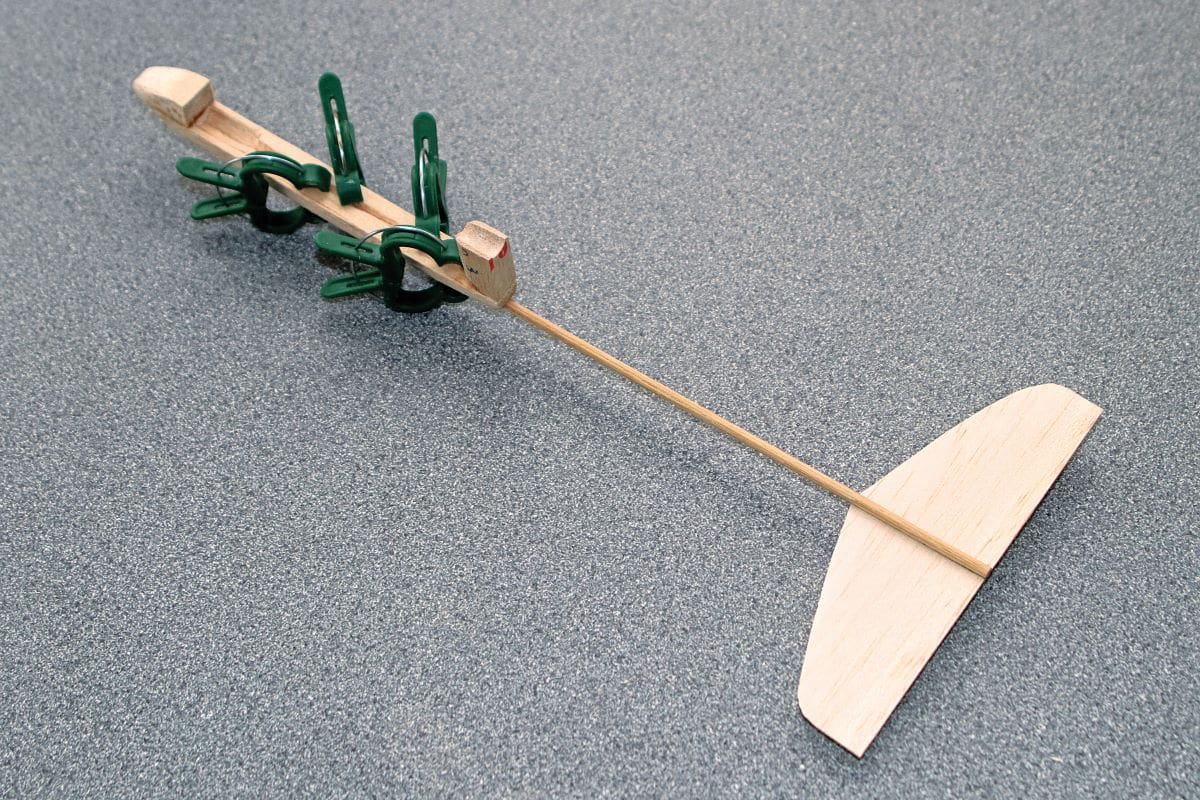
I pondered the best way of making a lightweight but rugged fuselage structure – in particular how to address the tail boom. I thought about 3mm carbon fibre tube and then considered a piece of 1/8” square spruce, before eventually stumbling upon a bamboo barbeque skewer – perfect!
I sanded a flat on one end of the skewer and glued the tailplane in place. The fin sits in the angle formed on one side of the tailplane as it lies beneath the skewer and is CA’d in position.
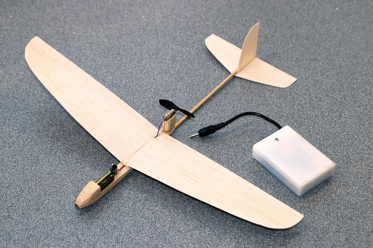
I elected to make the front fuselage pod from balsa scrap, with the capacitor UHU glued in a simple recess on top. The teeny pusher motor sits on top of a balsa pylon aft of the wing. The top of the pylon was assaulted with a round file to create a home for the pusher motor.
The final step was to retrieve the wing and sand the centre joint flat on the underside, and then glue it on top of the fuselage between the capacitor and motor pylon. The little model weighed in at 14g – a whole 2g lighter than the foam original.
Woohoo!
IT FLIES!
A few days later, I found myself at the field on a rare flat calm day, which seemed an ideal opportunity to test the new toy. Initial test glides showed the need for a pinch of nose weight, which cured the stalling tendencies nicely.
Time to add some charge into the capacitor. A few seconds connected to the triple AA charge pack saw the model climbing out and then levelling out and circling at around 20 feet altitude for over a minute, before gently sinking back to earth again. Repeated flights saw the pattern replicated.
So, it’s a toy, but so what? It’s a tiny slice of aeromodelling, combining a dash of trad. balsa fettling with a new (to me) power system. I rather like it! I know I’ve said it before, but it really is refreshing to have broken out of my electric rut and to have explored alternative methods of model propulsion.
See you next time.