- This plan article was first published in 2003
- Electric flight technology has advanced rapidly since and it is suggested that builders fit a brushless powertrain or seek set-up advice in the forum
- The plan, cowl and canopy can be purchased at www.myhobbystore.com
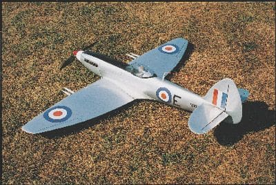
Released in March 1945, too late to see action in W.W.II, the Mk.22 was almost the last of a line that could trace its heritage back through six years of war during which it flew under a host of flags and fought on several fronts. During this time, the Spitfire’s performance evolved dramatically: from the 1030bhp Merlin III-engine Mk. Ia, it grew into the 2000+bhp Griffon-engine aircraft whose top speed was 35% greater and which, despite being 40% heavier, climbed 80% faster. Even so, the late bubble-canopied versions retained the Spitfire’s essential character in the lines of their elliptical wing and the tapered noses. And that, of course, is what makes the Mk.22 such as splendid subject for modelling.
FAITHFUL FORM
Usually, when I’ve built fun fighters from this era, I’ve had to increase the tail and fin areas in the interests of stability – I don’t see much point in making a model that’s built to scale but uncomfortably twitchy to fly. With the Mk. 22, however, I was able to retain the scale outline as the original itself featured larger tail surfaces than most earlier versions. Having said that, the areas of the elevators and ailerons have been reduced to suit the needs of the model: scale control surfaces would have caught the airflow like proverbial barn doors! For the same reason, I’ve limited the rudder deflection, although the control surface itself is of scale size.
Enjoy more RCM&E Magazine reading every month.
Click here to subscribe & save.
WINGS
After experimenting with built-up structures, I settled on foam construction for the wings, each of which is now made of two foam panels with veneer skins. These, incidentally, are available from the Nexus Plans Service (see the Datafile for pricing and purchase details). Also, in arranging for the dihedral to extend from the centre of the fuselage, I’ve obviated the need for the flat section across the Spitfire’s fuselage, all of which should simplify construction.
Begin by joining the two panels that comprise each wing half, checking that the washout is the same for both halves, and then add the 1/4” false trailing edge. The t.e. is grooved along its centreline to create a channel for the 14swg aileron torque rod. At the ‘elbow’ in the trailing edge, where the inner and outer wing panels join, you can cut the slot for the torque rods using three hacksaw blades taped together.
To avoid the risk of stiction, I chose to run the torque rods in sleeves made from plastic drinking straws of the sort you find on childrens’ drink cartons. Mechanically, they’re not ideal, but they do the job, especially if you epoxy them securely to bearers set along the sleeves’ run; you can either buy these bearers (Flair make them in 14swg), or you can make your own from pieces of plastic tube. The slight spring in this gauge of torque rod, by the way, doesn’t cause any control problems owing to the modest forces on the ailerons.
Attach the 3/8” leading and trailing edges to the wings, and sand them to shape. The last job before joining the wings is to cut out the recess for the servo box (I actually replaced the three standard servos in the wing and fuselage with Hitec HS-81 units, which pared down the model’s all-up weight by just under 2oz.
When you join the wing halves, check that the dihedral is the same either side of the centreline; if you use 1/32” ply for both dihedral braces (which fit into pre-cut slots), they’ll be strong enough to do the job without the need for a wing bandage.
I used a set of Du-Bro aileron horns on the upstanding torque rod ends, but found their holes were slightly too large to give a good fit with the 14swg wire. So, for a slop-free fit, I soldered thin brass tubing onto the rod ends, then drilled out the horns and secured them with a grub-screw. Once again, a slightly less labour-intensive solution would be to buy Flair’s proprietary 14swg torque rod ends that use axle collars for location.
The finishing touches to the wings are the radiators and canons. The rads are attached by strips of 1/4” balsa glued on the inside of their front and rear faces, which are then PVA glued to the underside of the wing. This seems a robust enough arrangement to withstand landing forces; we did lose one of the canons, but these are just a push fit into the wing.
FUSELAGE
It makes life much easier if, initially, you build the fuselage as far as F3 and leave the nose forward of the ‘firewall’ to be added later. Note that in former F3, you’ll have to glue the side longeron in the upper portion of the double-size slot, using a piece of 1/4” sq. balsa as a temporary spacer in the lower portion. Later removal of the spacer will leave you with convenient 1/4” sq. holes, ready to receive the nose framework. The longerons themselves need to be correctly aligned (check this by standing the fuselage on the firewall and using a set square) and sufficiently rigid to hold the structure true until it has been sheeted.
Cover the lower half of the fuselage first, by soaking two slightly oversize sheets of 3/32” balsa in hot water and taping them into position while they dry to shape. Then, trim the upper edge of the balsa sheet to shape and glue it to the bottom half of the centre longerons. Leave the sheets’ lower edges proud of the flats on the formers – you can trim them to shape when you come to fit the 3/8” underside sheet. This also saves you having to worry about two joint-lines at the same time.
Now’s the time to fit the wing-nut bracket, the servo tray and receiver box, and the snake supports. You can then install the snakes for the elevator and – if you’ve chosen to articulate it – the rudder, before adding the 3/8” sheeting to the top of the fuselage.
Wing fairings are made from soft balsa block, and look the part even if they’re slightly under-scale (though at 2oz each you don’t want to go overboard here). Rather than trimming, shaping and sanding odd bits of balsa in order to produce a smooth fairing line at the back, I used a lightweight filling compound (Microballoons) mixed with wing-skinning epoxy from Cherbourg Model Express. Applied with an appropriately shaped piece of card, a good smooth finish can be achieved which can then be treated with tissue and dope or fibreglass to give a suitable surface for painting.
NOSE & TAIL
With the fuselage finished, you can now add the front structure. Slide the two side longerons into place and fit F1 and F2, ensuring that they’re aligned with the rest of the fuselage; a piece of 1/8” balsa temporarily glued in place of the fin gives the old Mk.1 eyeball something to sight against.
The fin and tailplane, meanwhile, are made from 3/8” soft balsa sheet, whilst the rudder and elevators, which are hung on Mylar hinges, are made from 1/4” medium grade. Flying surfaces should be planed or sanded so that they taper from 3/8” at their root to 1/4” at their tips. This not only creates a less draggy shape than flat tail feathers, it looks much better – and when you’re building something as pretty as a Spitfire, it just has to be worth the extra effort, surely?
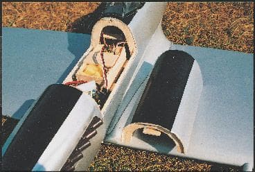
MOULDINGS
The mouldings for this model (available from the Nexus Plans Service) are all from ABS plastic, which can be readily glued and filled. Humbrol’s filler works particularly well with this material, the only drawback being that it’s grey, which dictates using a white undercoat before you paint it.
The air intake and radiators are all two-piece mouldings, though there’s plenty of spare ABS flashing if you need 3/8” strips to bridge the joints. To make a slip-in joint between the engine cowl halves, simply glue strips of proprietary styrene sheet (which is smoother) to the two mouldings.
MOTOR & PROP’
Before deciding on a motor / prop’ set-up, I experimented with a number of combinations, some of which proved very disappointing: one motor that cost three times as much as a standard can item, not only weighed more but gave only a slight increase in thrust in return for a significant increase in current draw.
The combination on which I eventually settled was a standard 600 driving an Aeronaut 121/2 x 10” prop’ through a JP 3:1 inline gearbox.
The battery is Sanyo’s 10-cell 1700mAh NiCad, which is as compact as an eight-cell sub-C pack and only 2oz heavier. This set-up produces 21/2lbs of static thrust at 19A.
Why the gearbox? Well, I did try driving a 9 x 5” prop’ directly, but found that although the thrust was the same as the larger prop’, the current draw was higher. I know that gearboxes are primarily thought of as a means to increase thrust by running larger props, but my tests tell me that any gains from using a bigger fan are offset by the mechanical losses in the gearbox, which can be as much as 20%. The JP ‘box, then, is really earning its keep by reducing the current draw.
When it came to fitting the motor / gearbox unit, I found that the boss on the front of the motor was slightly too deep and fouled the inside of the gearbox: gluing four thin washers to the front of the can provided the necessary clearance. To make sure that I didn’t over tighten the screws that hold the motor to the ‘box and cause the gears to bind, I applied a low voltage to the motor and tightened the screws until the revs began to drop, then backed off the threads a fraction.
If you’d like to conduct some engine / prop’ tests of your own, you can use a simple jig like mine: I suspend the aeroplane by its wings on two loops of string and attaching a spring balance to the back. It sounds a bit Heath Robinson, I know, but the results are the same as those obtained by a colleague who uses a rather more sophisticated rig! Anyway, if you come up with a more effective drive combination for the Spit’, please let me know.
NO MORE CAMOUFLAGE
To finish, I fibre-glassed the fuselage and sprayed the whole model with Japlac. Although I think the result was worth it, this process added 2oz to the model, so next time I’ll probably cover the fuselage with Solarfilm and only paint the wing fairings.
The silver colour scheme is based on the aluminium finish of some post-war Spitfires. Now, it may be because in the immediate post-war period Spits were being eclipsed in the front line by the glamour of jet fighters, but I found it difficult to track down information on these late-model aircraft. In the end, Hendon and Duxford came up trumps, and were able to supply not only photographs, but also a full-size example in the shape of Duxford’s VN485 Mk.24 (essentially a Mk.22 with extra fuel tanks and under-wing rocket rails). I’ve used Precision Markings’ decal set to dress the aircraft in the colours of the Mk.24s that flew with Royal Auxiliary Airforce squadrons based at Kai Tak in Hong Kong.
The silver finish might not appeal to you, of course, in which case the second volume of SAM Publication’s Modellers’ Data File No.5 should provide you with plenty of inspiration for other schemes.
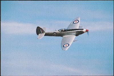
TAKING TO THE AIR
After all the work that went into building the model, and the anticipation of the first flight, the event itself was something of an anti-climax – everything worked!
Rather than hand-launching the model, I’ve make a dolly in which the aircraft sits slightly nose-down, giving the tail room for manoeuvre when the model rotates. After a take-off run of just 10 – 15 paces, the Spit’ simply hopped off the dolly, held level as it built up speed, and then climbed out. The darn thing just flew around as if it had been up there many times before: balance was pronounced OK by my club examiner and ‘test pilot’ John Witham, and I don’t recall any trim adjustment.
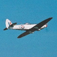
When tested, the stall proved to be a very modest affair: the left wing dropped just a fraction though that could have been my fault – I hadn’t balanced the aircraft laterally. Rolls were fine, as were the loops, though these had to be kept fairly compact otherwise she fell off the top. John was obviously confident in the effect of the washout as he made his turns onto finals quite tight. The Spit’, however, showed no inclination to drop a wing despite the whisper of throttle on which she was flying. Indeed, in the last few yards of flight we had the usual ‘No mate, I’m not landing yet’ business as the model floated off down the runway! Initial touch-downs ended with the model sliding along on the air intake and radiators, but as we refined the technique we found it was possible to virtually drop it onto the grass by simply holding the nose up until she stopped flying.
After his flight, John gave the Spit’ the nod. When I took the sticks, I found that the model flies just the way I’d hope she would, and her scale speed means she looks great, too. I couldn’t have wished for anything better.
DATAFILE
Designed by: John Lockwood
Wing span: 49''
Wing area: 3 sq. ft.
Weight: 4 1∕4 lbs
Wing loading: 21 oz / sq. ft.
Motor: 600 can
Battery: 10-cell 1700mAh 4/5C NiCad
Controller: Kontronic 30A