Please note that the article below is published to assist those building the Tornado. Nigel wrote the article in 2004 since when cheap brushless motors, ESCs and Li-Po batteries have become commonplace effectlively replacing NiCD and NiMH cells along with brushed motors and gearboxes in most applications. A 400-600 watt brushless power system is suggested for this model. The supplier contacts Nigel mentioned are reproduced but availablility can’t now be confirmed – Ed.
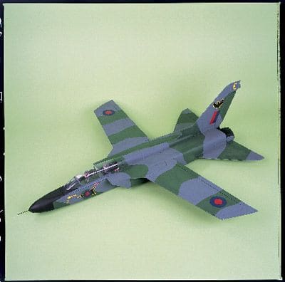
I’d previously dismissed the Tornado as a subject; having seen full-size examples in flight with wings swept back, drop tanks and weapons fitted, it just didn’t seem practical. However, witnessing a stunning display given by a Tornado at the Families Day at RAF Linton-on-Ouse completely changed my impression of the aircraft – this example was completely clean and did large sections of the display with the wings in the fully forward (i.e. 25º of sweep) position. It looked and sounded awesome.
Since 2004 marks the 30th anniversary of the Tornados maiden flight, back in 1974, its’ quite fitting that we feature it now as a celebration of its sterling service over the past three decades.
DESIGN CHALLENGE
Whilst the completely different airframe layout threw up some interesting design challenges, it’s interesting to note that the end product has a wingspan of 45″ and is 7″ wide at the jet pipes, whereas the full-size spans 45 feet and is approx. 7 feet wide at the jet pipes! A fact I discovered only after the design was finalised. So, although this is by no means a true scale model its somewhere around 1/12 scale in overall dimensions.
Past projects have taught me that some modellers would never have a jet model with a prop on the front, whilst others are still dubious of pushers… you just cant win! So, in order to solve the problem I designed the aircraft for either set-up; by having two optional battery compartments the Tornado will balance perfectly with one motor in the front or two pusher motors at the back, the flight battery being at the opposite end to compensate in each case. The model is basically a conventional fuselage within two hollow side pods. Not only does this make it quick and easy to build, it’s also sturdy and light.
POWERTRAIN
Until now I’ve always presented my designs to give excellent performance with cheap ‘can’ motors but with the structural integrity to take brushless power. Indeed the Tornado will fly on a good pair of 400 pushers but at the end of the day the Tornado is a fast jet and the model deserves to have a performance that will do it justice. So, this time around I’m offering the design as brushless specific, with the option of using cheap ‘can’ or buggy motors if your’e happy with a less exciting turn of speed.
Of the thousands of 45″ Tucanos built, most have been fitted with an AXI 2820/10 or the more recent equivalent conventional brushless motors that can be supported at the rear of their ‘can’. To power this model with 400-size brushless pusher motors you’ll need a separate speed controller for each, unless you decide to use a Kontronik twin drive set which uses one controller for two motors. Either way you’ll not be disappointed as this model is guaranteed to put a smile on your face. Both set-ups will give good vertical climb using the recommended gear, even on everyday 8- and 10-cell flight batteries.
ALL ABOARD!
Balsa selection is all-important. Set a target weight for each sheet you buy and think nothing of taking those digital scales into the model shop. Much of the Tornado is built from 3/16 x 3 x 36 sheet; aim for 30g per sheet or thereabouts.
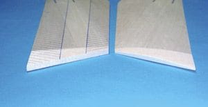
We’ll start with the wings, as these will be used for spacing purposes later on during the fuselage build sequence. On a flat building board, assemble the wing panels using the 1/8 spacers between them (medium cyano is ideal for this) leaving suitable slots for the 1/8 spruce spars. Sand the outer edges so that the tips meet squarely along their entire length. The tips can be attached with either epoxy or cyano, but if using cyano dampen the mating edge of the wing panels beforehand as this will allow the adhesive to penetrate far better. With the panels assembled, mark the profiling lines (see pic above) onto the upper surface. It may also help to draw a line along the leading and trailing edges to show the respective 3/16 and 1/8 limits – these are important for the later stages and must not be exceeded!
Using a razor plane and finishing with abrasive paper, profile each panel so that they end up with a smooth aerofoil section like the example shown on the plan. Note: it’s important not to round-off the leading and trailing edges at this stage. Clean up the root mating surfaces so that the panels meet squarely along their whole length and check that each root has the same profile, making adjustments as necessary. When satisfied, use epoxy to join the wing panels flat, i.e. without dihedral. When the epoxy’s set, trim the two spars to fit and glue in with PVA. When dry, sand the spars level with the upper and lower wing surfaces. Nothing more needs to be done to the wing at this stage so put it to one side for now.
FUSELAGE FROLICS
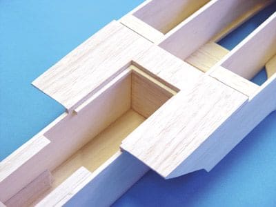
Those who built pre-production Tornado kits (something that’s now a regular part of the development process) all commented on how simple the fuselage is to make despite its unusual shape. Begin by removing the hand grip cut-outs from the outriggers and butt-join them to the main floor such that the rear edges line up. Chamfer the rear inner edges of the fuselage sides so they meet squarely at the fin support when pulled together. The two fuselage sides can then be glued onto the main floor using formers F1 and F2 to keep them parallel; start from the front and apply glue only as far back as the rearmost extent of the hand grip cut-outs and ensure that the rear edges are flush with the floor panel.
Glue F1 and F2 in position, add the handgrip reinforcement piece to the floor (positioned between the hand grip cut-outs) and pull the rear of the fuselage sides onto the fin support to check alignment. Glue F4 in place, making sure it’s absolutely central and perpendicular to the main floor. Ensure that the unglued portion of the fuselage sides are still level with the floor. Note that when pulled in, the fuselage sides will no longer reach the back edge of F4 due to their curvature. When this arrangement is complete, carefully chamfer and add F3 before running thin cyano along the unglued portion of the fuselage side-to-floor joint.
Make two side pods and add suitable lengths of 3/16 square balsa to form the tailplane support rails, which should go above and below the tailplane slot. Leave a suitable size gap in the lower rail 60mm from the rear edge where the elevator servo will be fitted and mark this gap on the outside.
The elevator servo slots can also be cut out now if desired, saving a fiddly job later on.
Add the side pods, noting that they butt onto the outer edge of the outriggers (i.e. their lower edges will be in contact with the building board). Glue two 50mm lengths of 3/16 strip between the pods and fuselage sides near the front to maintain integrity whilst working on the rear of the model. Then, glue four 12 lengths of 12mm triangular stock in place at the rear inner corners of the pods – these will facilitate rounding of the rear end later. Glue the rear upper deck pieces in place leaving a parallel 3/16 gap in the middle for the fin. Use the notch in F3 and the gap above the fin support as a guide. Glue a 3/16 square x 90mm long spacer into the front of this gap to determine the fin assembly position later.
It’s far easier to do the rear fuselage rounding at this stage, so, working rearwards with a razor plane and abrasive paper, progressively round off the corners top and bottom. Note that the degree of sanding required increases from practically nothing at the forward-most point of the upper deck, breaks through to the triangular stock at about the beginning of the tailplane slot, and finishes with a curve that matches the radius of the vacuum formed jet pipes.
Next on the agenda is to cut out the radio access hatch, which originates immediately behind the hand grip reinforcement. The hatch is 150mm long on the pusher version, 250mm long on the tractor (to allow flight battery fitting) and is secured using a ply tongue at the rear and two hardwood blocks and screws at the front. Glue strips of 3/16 square to the inner faces of the fuselage sides to support the hatch along its length. Fabricate the two stabiliser halves noting grain direction, and round off their leading edges.
Temporarily fit the wing squarely and centrally, then mark both the front extent on the fuselage sides and side pods and the inboard aileron extents 5mm out from the side pod edge.
Check that the forward edge of the upper deck exactly matches the sweep of the wing trailing edge and that the wing touches each fuselage and side pod edge. If it doesnt, use a sanding block to correct the situation.
Article continues below…
Enjoy more RCM&E Magazine reading every month.
Click here to subscribe & save.
With the wing held / pinned temporarily in place, slide the stabilisers into their slots and check they’re level – make slight adjustments if necessary. When satisfied that all’s well they can be securely glued in place. Taper the elevators to 3/32 thickness at the trailing edge and bevel the leading edges to allow 10mm movement each way. Decide on your preferred hinge method but don’t hinge permanently until the coverings complete. Notch the inner edges by 1/16 and fit the ply horns.
With the wing placed on a flat surface the ailerons can now be carefully cut out and their trailing edges rounded off. They must both be exactly the same length, i.e. 400mm.
Chamfer the l.e. of each aileron to allow 10mm movement each way and decide on your hinge method. Some prefer film or tape hinges, while others use either Mylar strip or flocked paper cyano hinges; all are acceptable provided they allow free movement. Whatever your choice, dont finalise the hinges until after covering. Next, notch the inner edges of the ailerons and fit the ply horns. Oh, and in case youre wondering, don’t round off the wing leading edges just yet!
AIR INTAKES
Cut three pieces of 3/16 square and line the bay in front of former F2 to provide support for the canopy floor. Trim the air intake tops so they meet exactly in the middle (behind F2) whilst leaving the lining strips completely unobstructed (see photo), then glue them in place ensuring they overhang at the front. Using a razor saw blade, cut a chamfer on the leading edge of each intake top such that it lines through with the raked forward edge of the side pod. The 3/16 diagonal strip at the leading edge of each outrigger can now be cut to length and chamfered to sit squarely against the fuselage side and the side pod, blending in with lightweight filler if desired. The air intake is completed by adding the 1/8 sheet triangular floor piece, then rounding off all sharp edges to finish.
FRONT END
Cut four 6 lengths and four 3 lengths of 10mm triangular balsa. Two of the 3 lengths should be glued in place in the bottom corners behind F1, the other two should line the top of this bay in a mirror image. Before gluing, the four 6 lengths will need chamfering at the rear to accommodate the angles imposed when the nose is pulled onto either the motor mounting disc (tractor version) or nose block blank (pusher version). If building the tractor configuration, carefully sand the front fuselage edges so that when attached the motor disc will give 3º of right-hand side-thrust but no down-thrust. When satisfied glue it on firmly with a generous helping of epoxy.
Add the floor and when set, shape the lower half of the fuselage progressively to the front. Note that during this process youll break through to the triangular section, which is intentional.
For the tractor version, dummy fit the motor. If using a conventional brushless set-up such as the Tornado 3630, it should be supported at the rear end of the can using scrap 3/8 balsa across the lower floor to avoid the motor mounting disc from being compromised with the downward momentum of a heavy landing.
Glue the upper deck in place, noting that the gap between the rear of this part and F1 gives motor access. Trim the canopy floor with two notches at the rear so that it slides snugly between the air intakes, and sits flush with the front upper deck. Starting just forward of the air intake tops, shape the nose until its nicely rounded at the front yet has a flat area for the canopy. If this has been carried out correctly the canopy floor will be rounded at the edges and youll have broken through to triangular stock near the front. Do double-check, however, that the cockpit floor beneath the canopy is completely flat.
FAIRINGS AND GUSSETS
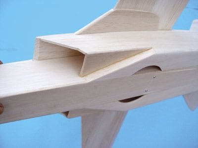
After giving the whole fuselage structure a light sanding to remove any unwanted marks, the wing can be firmly glued in place. Glue the wing gussets from the l.e. to the air intake such that theyre attached 1/16 below the top surface to allow for the wing-sweep fairings. If the wings been profiled correctly there should be a 1/16 step between the rear of the wing and the rear deck and a 1/16 step at the front of the wing and the air intake tops. Trim the 1/16 over-wing fairings to fit exactly into this recess, and when sanded there should be a smooth, continuous upper fuselage surface. Add the upper wing-sweep fairings, which should completely cover the gussets, and butt-join with the over-wing fairings, blending in with a little lightweight filler if necessary. Oh, and dont forget to fit the lower wing-sweep fairings! The thick portion where the fairings sandwich the gussets can now be sanded to a rounded l.e. profile as can the rest of the wing l.e.
FIN AND TURTLE DECK
Assemble the six parts of the fin, noting grain direction and rounding off all leading edges. The cross grain piece not only adds scale detail but also helps to avoid warping of the large surface. If you’re going to fit the (optional) rudder then mark and cut it out, shave 1/16 off one end for clearance and bevel the l.e. to allow 25mm movement each way. Decide on your hinge method but dont permanently hinge in place until after the model has been covered. Cut a small slot in the rudder and glue the ply horn in place. The rudder is operated by snake or pushrod from a servo accessed via the lower hatch.
Push the fin assembly down into the gap left between the upper deck, locating with the notch in F3 and the top of the fin support, sliding it as far forward as the 3/16 spacer will allow. Making sure that its absolutely vertical, glue the fin firmly in place.
The rear turtle deck can be made up from very light 3/8 sheet carved to shape, or by making a framework skinned with 1/16 sheet. That said the moulded item available from Highbury Leisure (along with the clear canopy and black jet pipes) is without doubt the simplest route. Either way, check that it lines up perfectly with the rear of the canopy before finally securing in place.
CANOPY AND DETAIL
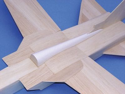
Cut the canopy and offer it up to the balsa floor piece, ensuring a seamless transition with the rear deck. Don’t forget the crew; lightweight pilots and cockpit interiors designed specifically for this model are available from Vortex Plastics on 01162 207080. When completed to your requirements, glue the canopy and interior firmly in place. Clear canopy glue or epoxy are probably the best choice of adhesives for this.
For the tractor version, trim the jet pipe mouldings and line them internally with soft 1/8 end-grain strips to increase the adhesive area for gluing to the back of the model. If necessary, dampening will help the strips achieve the curvature required. When dry, sand any excess off the rear face. Don’t forget to cut out the rear circle to allow airflow through the model and thus reduce drag. Also, remove the 250mm lower hatch and fabricate the flight battery bay.
If making the pusher version, epoxy the 4 motor mounting dowels in place with sufficient protrusion for your chosen motors. The rear ends of the dowels should be tapered slightly to allow the jet pipes to fit correctly. In this configuration the flight battery will be housed beneath the cockpit.
It’s better to attach the motors and test-fly the model without the jet pipes, adding them later when satisfied that all is well (rather than having to cut them off if its not!)
Either way, the hourglass-shaped piece of 1/16 ply between the jet pipes will finish off the rear end nicely.
Reach this stage and youll be admiring a basically complete bare airframe that should weigh in the region of 16oz, or 18oz with all mouldings fitted.
Article continues below…
By now you’ll hopefully have a bare airframe ready, weighing about 18oz, and crying out to be covered. Whilst covering is a matter of personal preference, the prototypes have been either Solarfilm finished or covered in silver Easycoat and then airbrushed after a wipe with Prymol – it really doesnt matter what you choose as long as you keep a keen eye on weight. Look on the Internet and theres an abundance of attractive colour schemes that various countries have used, certainly the German Air Force (Luftwaffe) have been the most inventive – the elaborate Tiger meet examples are a lot of work, though!
The example featured throughout these two articles was finished using Humbrol enamel over silver Easycoat, the scheme depicting an RAF Honington Tornado GR1 from the late 1980s. All roundels and decals are cut from either Solarfilm or Solartrim, though if you dont fancy the work, then Overlander (01524 793328) can supply an identical decal set for this colour scheme, complete with nose arrow and fin bat. The pilots and cockpit interior are also available as a specific set from Vortex Vac Forms (01162 207080), so if you really wish to go to town on your finish then all the bits and bobs needed are only a couple of phone calls away. Panel lines have been applied using an HB pencil to give the desired effect but without going over the top, as this can spoil a nice model if overdone.
RADIO GEAR
This model is really designed for use with a computer transmitter, although it is possible to get away without as long as you can find two opposite-sense servos for the elevators so that when joined with a ‘Y’ lead they will operate the elevators up and both down in unison!
Failing that, one elevator servo can be mounted about 5mm lower with the pushrod operating from the top of the output arm, which has the same effect as reversing the rotation.
Each control surface has a separate servo operating it, which allows the mixing of ailerons with tailerons if you wish to increase the roll rate, or elevators with flaperons if you want to emulate those breathtaking high-alpha passes that Jaguars and Tornados do with such presence! The rudder is an optional function, although anyone building the tractor-powered version should seriously consider fitting it as the rotating vortex effect brought about by a large prop and large fin requires a good bit of right rudder in full power situations (such as vertical climbs etc.) to keep things straight. Pusher versions will only need the rudder for 4-point rolls or top-rudder passes, but you can take it or leave it as the Tornados really more of a bank and yank type model anyway.
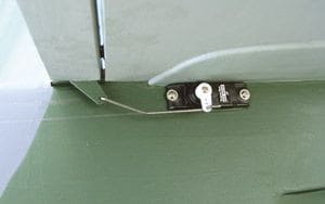
The aileron and elevator servos are recessed into the side pods just under the wing and tailplane, so they’re pretty inconspicuous from most angles. The short pushrods are simple 18swg piano wire with a Z bend in one end and an adjustable clevis on the other.
Whilst the aileron servo leads (pushed through holes made in the inner fuselage sides) will reach the receiver, you’ll undoubtedly need short extensions (or a long ‘Y’ lead) for the two elevator servos.
The rudder servo can be mounted within the radio bay and hooked up using a snake or pushrod. Alternatively, it can be recessed into the rear upper deck and a small pushrod employed in the same way as the other control surfaces.
The receiver is secured inside the radio bay using Velcro, with the aerial wire exiting through the side pod and taped along the underside of the wing to the tip, which should leave very little excess trailing behind.
Movement of ±10mm is about right for the ailerons, but dont overdo the elevator movement as theyre very powerful; ±6 – 8 mm will probably be sufficient. If the rudders been fitted then get as much as you can out of it… ±30mm will make it responsive without being at all violent. As with any new model the test flight will give you an instant feel for the movements, which can be adjusted later to personal preference.
POWERTRAIN – PUSHER VERSION
Article continues below…
As explained previously, this model can be powered either by one 600 BL in the nose or two 400 BLs in the rear. Its difficult to choose between them in performance terms but certainly if noise is an issue the tractor version is far quieter than the pusher.
That said, the howl of the pusher, with two 4.7 x 4.7 props turning in excess of 22,000rpm each, all adds to the excitement – and this configuration is my particular favourite. Unless using the Kontronik 400 drive set (which runs two Fun 400/23s from a single Smile 40A ESC) youll need a separate controller for each motor, so here again the tractor version comes up trumps in that it works out a lot cheaper.
As you’ll possibly have read the aptly named Tornado 2815/2900s were specifically wound for this model, and on eight GP3300s the performance is excellent. Mega 16/15/4s are also good but will need 10 cells, which isn’t ideal; use 10 x GP3300s and you’ll feel the extra weight, use 10 x 1700CPs and duration will be pretty poor. The 16/15/3s on 8 cells are just a little hot due to their higher kV.
Remember also that there’s only enough clearance for props of about 5″ diameter – a pair of APC E 5.1 x 4.5s will just clear each other. The cheapest route, however, is to use a pair of Irvine carbon Gunther copy blades on Ernie Thorpes lovely little adaptors. Graupner Cam Speed and APC E props are available in 4.7, 5 and 5.2 diameters with a variety of pitches available, so it’s worth experimenting to find the best set-up for the motors you use.
My favourite arrangement is a pair of Tornado 2815/2900s on eight GP3300 cells and a brace of APC E 4.7 x 4.2 props; the sound is awesome, performance is just right and flights last about 8 minutes of mostly flat-out flying.
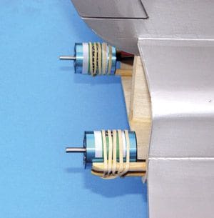
One thing to remember with any brushless set-up is the importance of keeping the battery-to-controller wires as short as possible; inductance spikes that can cause nasty radio glitches will build up if these wires extend beyond about 8. Due to the length of this model the wiring has to be quite long, so it’s the motor wires that should be extended. I generally twist mine tightly and bind with tape every few inches to keep the twist in place. The ESCs are fixed using Velcro within the side pods just above the hand-grip holes. Ideal, as the position gives good access and the constant airflow allows them to work efficiently.
The two motors simply tape to the dowels to stop fore and aft movement and are secured using either cable ties or elastic bands. Note that the dowels may need to be chamfered at their rearmost extents to clear the jet pipes, which are lined with 1/8 end grain to give plenty of adhesion area when gluing in place. Allow a decent bit of clearance between the prop blades and the mouldings as this will help keep the model a little quieter.
The flight battery fits under the canopy hatch, with a suitable aperture made in F2; securing is down to personal preference but a Velcro strap is probably the ideal way to go. Remember to make up a pair of battery lead ‘Y’ adaptors to operate both controllers at the same time.
People often ask about the implications of using BEC with two controllers, and it seems to be a bit of a grey area. The two Jeti 18-3P and 30-3P-equipped prototypes use a ‘Y’ lead into Rx channel 3 without any problems, and indeed as well as spreading the load between two BEC circuits it also provides limited belt and braces should one ESC go u/s – although running five servos from one BEC is definitely not recommended!
TRACTOR VERSION
For the very same reason the tractor version, having only one ESC, should really have an independent Rx power supply. A small, separate battery is okay but weight and recharging are annoyances. However, the amazing little S-BEC (from www.aircraft-world.com) weighs next to nothing and will power five servos from 10 cells all day without fuss, indeed this is what was used on the prototype. Some stand-alone BEC units can cause all sorts of interference problems as they are themselves high-frequency generators which need to be kept as far away from the Rx as possible. However, the new S-BEC has barely traceable radiation and has proved completely reliable in operation.
The S-BEC is wired to the same gold connectors as the speed controller, but plugs into the battery socket of the Rx; if using a BEC controller this must be disabled by disconnecting the positive wire in the Rx lead (usually the red wire) so that the S-BEC and the controllers BEC circuit don’t conflict with each other.
As featured last issue, an ideal tractor motor for this model is the Tornado 3630/1000, which can be propped for either 8 or 10 cells depending on your preference. Being completely conventional it can be supported at the rear of its can making a very solid installation, and a single 40A BL controller is more than adequate for most applications.
Article continues below…
The flight battery needs to go in a recess built in the rear of the model to achieve balance which, once again, requires extended wires. Follow the same rules as above by extending the motor wires and you should have no problems at all. Velcro the controller in one or other side pod for cooling purposes, with the battery wires threading out through the inner fuselage sides and the extended motor wires threading back into the fuselage near the front of the side pod, to the motor. It can be a bit of a fiddle getting this wiring in place but once installed it should be a completely service-free installation. Make sure that the prop and spinner are nicely balanced, especially if using an outrunner type motor.
IN-FLIGHT ENTERTAINMENT
All-up weight can vary from as little as 3 lb 4oz (using ten 1950 FAUPs, Jeti 18A 3P controllers, 1.5mm motor wire and a pair of Tornado 2815/2900s) up to 3 lb 10oz with the 3630/1000 and ten GP3300 cells, so anywhere within this range is acceptable. Any heavier and youll feel it in the vertical manoeuvres, especially with the twin pusher version where the small props are less efficient. Incidentally, my favourite set-up (two Tornado 2815/2900s and eight GP3300s) comes out at around 3 lb 6oz.
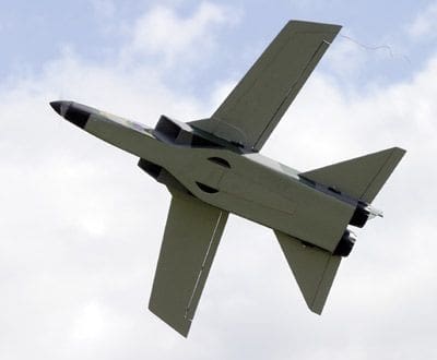
Even at 45″ span the Tornado is quite a sizeable model due to its large volume. Although the same span as last years RCM&E Tucano, stand them together and the Tornado dwarfs the Tuc! The Tornado also has considerable surface area, and more surface area means more drag; having airflow through the intakes probably helps matters here but this model needs a good bit of power, hence the reason for it being presented as a brushless-specific project. Its not designed to be fast, more to cover the sky at a realistic, scale speed. At 1/12 scale a 50mph pass relates to a 600mph pass by a full-size Tornado – and thats shifting! To make the model really fast youll need a pretty hot brushless set-up. This is because it appears to reach terminal velocity in a similar fashion to the legendary Avonds F-15 ducted fan version.
The Tornado is extremely stable, a fact that I suspect is due to the airways cutting channels in the air, in the same way as a catamaran with two hulls cuts channels in the water. Whatever, its rock solid, cant be tempted to stall, and can even be hovered in a reasonable breeze without dropping a wing.
The C of G location shown on the plan is a completely safe starting point and can be moved back up to 10mm without altering anything much beyond control sensitivity. Too far and it’ll begin to hang its tail but she still wont flick on you; adjust the position of the flight battery as necessary and you’ll soon find the balance point that suits you.
TORNADO? PUSSYCAT!
This model is easier to fly than most low-wing trainers, being neither darty nor the slightest bit twitchy, so anyone with BMFA ‘A’ ability should have no problem managing it. Certainly the distinctive large fin and underside shape make orientation a joy, and despite not having the best eyesight in the world I’ve never had the slightest doubt about which way this model is going! If youve always fancied a jet type but been apprehensive about the speed or characteristics then this may be the one to join the jet set with, as it holds no surprises at all.
On a purely practical note, the position of the hand grip cut-outs make this model extremely easy to solo launch with the transmitter in your other hand. Lower powered versions may dip slightly but using the recommended set-up it simply hurtles away with authority – after a few seconds straight and level to gain momentum it can be pulled vertically up to a pretty good height – just like the full-size!
The elevator is quite responsive, but the ailerons have been deliberately kept small to limit the roll rate to that of the real thing – twinkle rolls just look silly on a fast jet model and this one is simply so stable it flatly refuses to flick! If you require a better roll rate, then increasing the aileron movement or linking ailerons with tailerons will do the trick. On a fast pass the twin brushless pusher version simply howls; the tractor version isn’t actually any slower but as the sound is totally different the impression of speed isnt quite as obvious. The flat sheet wing provides exemplary manners, and even in a crash situation the chance of any damage beyond breaking the nose off is extremely slim.
Throttle back and the Tornados nose automatically rises just like the real thing as the huge underside area comes into play, making landing approaches an absolute joy. Whichever power system is used, front or rear, the slow speed handling is completely predictable and shell float on and on with very little power needed to extend the approach.
Whilst the Tornado definitely justifies brushless power, it will actually fly on as little as eight cells and two Permax 400 6V motors; although performance is positively pedestrian, the design’s foolproof handling qualities mean it won’t catch you out. If you can stretch to nine cells and a pair of QRP Hyper RVs (from www.aircraft-world.com) you may be quite surprised! This is without doubt the optimum cheap can motor set-up and wont set you back more than a few pounds if you already have a suitable speed controller. A shot in the arm is to use a separate flight battery and controller for each motor – much more rpm!
When it comes to the tractor-motored version, the performance difference is nowhere near as noticeable, indeed the Fanfare 16-turn double on 10 cells and the 3.8:1 gearbox featured in Fly Electric recently isnt that far behind the 3630/1000 in vertical performance! What is different, though, is the sound – and to be honest a whirring gearbox simply doesnt suit this model at all. But, if that isnt an issue then the geared buggy route will give excellent performance for a lot less money than the brushless alternative. John Swain at Fanfare (01227 771331) is always happy to chat and is getting excellent feedback from those units already being enjoyed in the 45 Tucano.
AND FINALLY…
I hope you decide to have a go at this model. It really looks the part in the air and is a complete pussycat to fly, even for those with less experience. The secret to success, as always, is correct lightweight balsa selection. Even if the balsa appears too flimsy, remember the strength is in the design, not necessarily the materials.
For those who wish to see a full build sequence and have access to the Internet, visit www.bvrkits.com and click on the Tornado picture; this will take you to the specific homepage and you can navigate from there. There are also downloadable video clips of the two different power systems in action.
The Panavia Tornado has now been flying for three decades, and having served the RAF extremely well is to be replaced by the Eurofighter Typhoon in the near future. It remains one of the finest and most awesome strike attack aircraft in the world, and is very rarely modelled… this design is for your enjoyment, so get out there and have some fun!
DATAFILE
Aircraft type: Electric semi-scale
Designed by: Nigel Hawes
Wingspan: 45”
Wing area: 315 sq. in.
Fuselage length: 40
All-up weight: 3 lb 4oz – 3 lb 10oz
Wing loading: 23 oz / sq. ft.
Recd motors: 2 x 400 (pusher) 1 x 600 (tractor)
Recd battery: 8 / 10-cell Sub-C (or Li-Po)
Recd no. channels: 3 / 4
Control functions: Aileron, elevator, rudder (optional), throttle
Control deflections: Aileron ±10mm, elevator ±10mm, rudder ±25mm
Moulded parts: vacuum formed parts, including a clear canopy, rear fuselage fairing and jet pipes (ref. CANRC2021) are available from the Highbury Leisure Plans Service. Tel. 01689 886660 / 661 for prices or tune in next month.


