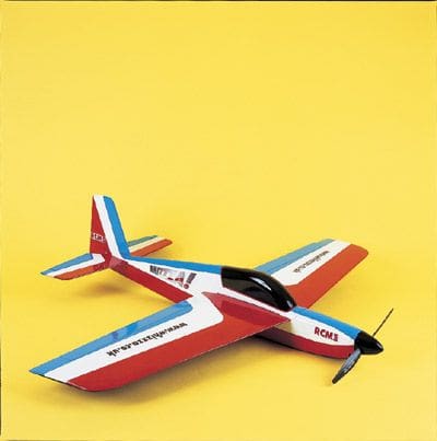
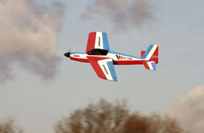
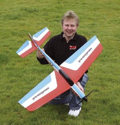
Whizzza is a 42″ span, direct descendent of my 32″ span Fizza featured in the May 2005 issue of RCM&E. Whizzza offers greater aerobatic capability coupled with the increased smoothness that only comes with a larger model, all assisted by a greater C of G-to-elevator moment. After a development journey involving several prototypes the design before you was born – easy to build and rugged, but with flight characteristics probably suited to the everyday club flier.
BUILDING
Anyone who built the Fizza will have a head start here as the basic construction bears great similarity.
Start with the wing, as it dictates the fuselage front deck position later. All wing panels are from 3/8 or 10mm sheet balsa and you’ll need to use the softest and lightest sheets you can find. At one time I preferred a fairly tough l.e. panel to resist the dings brought about by landing in stubble etc. but experience of the Fizza has shown that the hard dowel l.e. resists almost all such trauma, allowing considerably lighter panels to be used. Feedback from Fizza owners made me aware that a few builders struggled with attaching a round dowel to a flat balsa sheet edge, indeed, after sanding, the method also leaves a rather unsightly void just behind the dowel unless you actually bury the dowel into a groove in the l.e.
So, to make things easier on the Whizzza (but just as effective) Iv’e used 4mm square spruce instead of dowel, for two reasons – first, its flat edge glues more easily to the l.e. and theres no void after sanding. Second, 4mm dowel is almost impossible to source. All you have to do after profiling down to the hard spruce is to round it off slightly with a sanding block – job done.
There are two options for the wing spar: for general sport flying the short spruce item with balsa spacers filling the gap to the tips will be sufficient. However, if you intend to pull high-g, pylon-type turns then go for a full-length spruce spar; theres very little weight difference. Its probably a good idea to incorporate the full-length spar if you use particularly soft, light balsa for both wing panels as these will otherwise flex quite noticeably in flight.
When the panels have been joined with the spar between, add the spruce l.e. strip each side (leaving a suitable gap in the middle for the fuselage front deck) and glue the tips in place with epoxy. Draw the 60mm profiling line behind, parallel to the spruce strip, and profile the l.e. down to the spruce making a smooth, uniform section using a razor plane and sanding block. The square spruce strip is then simply rounded off. Theres no t.e. to profile, as the taper of the ailerons provides this. Whizzza uses hefty 10 x 45mm aileron stock which, if you cant get from model shops, is easy enough to make from soft sheet. With the ailerons held in place all that remains is to sand the rearmost area of the wingtips to match and you have a completed wing! A good panel will weigh 6oz (170g); any more than 7oz and you can be sure that the sheet youve used is far too heavy.
BODY LANGUAGE
The fuselage is made from light soft sheet, as the strength is in the design and not the materials used. Don’t be embarrassed to take your digital scales into your local model shop and come away with the lightest sheets they have.
Remembering to make opposites, glue the doublers to the fuselage sides; this is where a difference will be seen from the Fizza, as the doublers comprise of a short 1/8 sheet doubler at the front and two strips of 3/16 for the wing seat and access hatch reinforcement. The termination of these 250mm long strips dictates the main former position. The aperture in the main former that allows clearance for the aileron torque rod operation can either be made before construction begins, or at the very end when the wings fitted, i.e. when you can see exactly where clearance needs to be – your choice. I prefer to do it at the latest possible stage to maintain strength in the former during the fuselage construction process.
After fitting the flat-edge triangular pieces at the front, the fuselage is joined using the rear and main formers and front upper and lower sheeting, leaving the correct frontal area for the motor mounting disc. The latter should intersect with at least 1/8 (3mm) of the front upper sheeting and with the flat edged triangular pieces adding to the motor disc gluing area. Use epoxy to glue the plywood disc in place as cyano is too brittle and will result in an escaping motor after a few bumpy landings. Consider the type of prop adaptor youll use, and if necessary glue the spacing collar onto the motor disc and blend this into your chosen 2 spinner. The whole front of the model can be carved, planed and sanded to shape – dont forget the two triangular stock inserts within the air intake that should be shaped to a smooth, flowing mouth at the front.
The Whizzza fuselage construction differs again from the Fizza in that the upper rear fuselage is added later – this being preferable to fighting with very deep one-piece fuselage sides that require pulling together at both rear and top without them bowing out too much. They can be added one at a time after both the front and rear of the fuselage have been secured; slightly chamfering their lower edges to the required angle will result in flat contact with the upper edges of the existing fuselage sides. The slight angle at the glue joint can be lightly sanded out later as theres plenty of material in the thick fuselage sides to allow this.
After levelling the upper edge of the top decking with a sanding block, the rear upper sheeting can be added and sanded to a nice round shape, but without reducing its height at the rear.
Article continues below…
Enjoy more RCM&E Magazine reading every month.
Click here to subscribe & save.
TAIL UNIT & FINISHING
With the wing laid in position, fit the stabiliser to establish that its level with the wings, making slight adjustments to the stabiliser seat until things line up – when satisfied you can glue it in place ensuring equal distance between its front corners and the rear wingtip corners. If, however, you prefer to build and cover each of the major tail components first, simply assemble them off the model but do plenty of dummy fitting to ensure all will be level and square, as this is key.
It’s far easier to round off the stabiliser l.e.s before gluing them in place, as this reduces the risk of inadvertently marking the surrounding fuselage area. The stabiliser tips are then added and blended in with a light sanding. Dummy fit the elevators and join them with a piece of 3/16 dowel so that operating clearance exists to each tip; round or chamfer these at their l.e.s to allow the required up and down movement.
After lining it up both vertically and with the fuselage centreline, glue the fin in place (again, its far better to round off its l.e. first) and continue the fuselage line to the rear corner with scrap balsa blocks. These must be shaped accordingly first, as youll make a real mess of the fin and tailplane if you attempt to shape them after they’ve been glued in place! Time taken getting them right will result in a pleasing rear fuselage shape (helped along by a smearing of lightweight filler if required).
Use a fairly firm piece of sheet for the battery access hatch and retain it using your preferred method. I use the screw and securing block method with a thin ply tongue at the front, but it cant be stressed enough that the hatch securing system mustnt be relied upon for battery security. In a 600-size model where battery weight can be considerable, it must be secured independently (Velcro straps are a good solution). The rudder / elevator servo access hatch can either be made removable or simply taped in place after covering if access is considered unnecessary during the models useful life (do bear in mind you may need access in the event of servo failure or stripped gears).
Apart from a thorough all-over sanding to prepare it for covering, your fuselage and tail unit is complete, weighing in at less than 6oz (170g). Allied to a wing made from well-chosen balsa you should be looking at a 12oz bare airframe weight; 14oz is ok, but at 15oz shes getting a bit lardy! That said, as well see later this is a non-issue if you use a Li-Po flight battery because the saving in weight over NiCads or NiMHs will far outweigh the effect of a heavier airframe. However, the overriding message remains the same – use the softest, lightest balsa you can get!
COVERING & INSTALLATION
The prototypes were covered in either Solarfilm or Easycoat but you can use any sensible method you like. Solartex would possibly be a bit extreme, but Profilm is acceptable. Its easier to cover the wing separately from the fuselage / tail unit and then join them later. Furthermore, as the aileron linkage is specific to the wing, you can completely gear up the various linkages and attach the wing (using 5-minute epoxy) as one of the very last tasks – make sure it’s level with the tailplane and that the aperture made in the main former is sufficiently large to avoid fouling of the aileron torque rods.
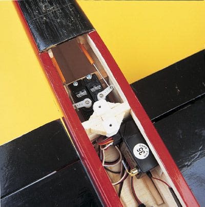
Snakes or pushrods can be used for elevator and rudder control, but be sure to use appropriate servos. Higher-powered Whizzzas will be capable of speeds well in excess of 100mph, so use something like the 12g Naromax BB micro servos for these surfaces. A decent mini-servo is recommended for the ailerons, such as the 17g GWS Park servo.
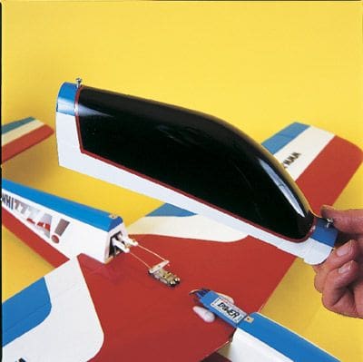
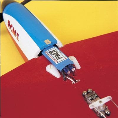
The speed controller sits on the front of the wing, keeping the internal wiring to a minimum and protecting it from an errant battery in the event of a heavy landing or crash. There’s a massive space for the flight battery, allowing the use of almost any size or type of appropriate pack and to achieve the C of G without resorting to additional ballast. Trim the moulded canopy to a nice snug fit over the wing and upper decks, and retain it using Velcro, tape or screws. The control surfaces should be hinged very firmly. I prefer to use either Mylar or flocked paper hinges and peg them with a cocktail stick, though a good quality tape hinge would probably be just as secure.
Article continues below…
SET-UP AND FLYING
Probably the most daunting thing about any electric model, especially to the newcomer, is the choice of powertrain. There are so many motors with confusing numbers on them, and then you have to choose an appropriate ESC with a decent operating margin. A battery capable of providing sufficient current and capacity will also be needed, and if a Li-Pos chosen itll need to have a large enough ‘C’ rating for the job in hand. Finally youll need to choose a prop that allows all the chosen items to work together in harmony- no wonder people get confused!
You’ll be glad to hear, then, that the Whizzza is very tolerant on set-up. It’ll fly quite happily on a 150W combo such as a Typhoon 15 swinging an 8 x 6 prop on a 3s KWT 2000mAh Li-Po drawing just 15A: with an overall weight of just over 11/2 lb (680g) it goes very nicely and would be an ideal intermediate model for anyone coming off a trainer – it really is that docile at lower weights and power settings. However, its tough enough to handle anything in the 250 – 350W+ range, and there are a number of suitable motors (e.g. AXI, Mega, Vortex etc.) that will be suitable – indeed I’ve flown prototypes using all of these. However, for anyone either starting off in electric flight or using the Whizzza as their first step up into the 480 / 600 brushless league, theres an ideal motor / controller combo that flies the model with fantastic performance, but wont put a big hole in your pocket!
The high quality, low cost Hyperion 3013-14 and X-Power ESC are available from BRC Hobbies at a special combo price for Whizzza builders of just £74.95 for the 350W set-up using the 40A ESC, and an amazing £69.95 for the 250W set-up using the 30A ESC. In operation these motors are super smooth, cool running and very powerful; using a 3s Li-Po and 10 x 8 Master electric-only prop gives excellent vertical performance on full power. Throttle back to a sport setting rather than out-and-out hooligan mode and they seem to be extremely efficient – I’ve had 30-minute flights out of a Polyquest 4400 3s Li-Po and the model wasnt hanging about at all.
Use NiCads or NiMHs and the overall weight is naturally higher, but the Whizzza takes it all in her stride – even on an 8-cell pack of GP3300 NiMHs the weight is only 40oz (1.1kg), equating to a very healthy wing loading of just 18oz / sq. ft.
Whatever set-up you choose, you’ll love the way the Whizzza flies. She can be as docile as you want, simply refusing to tip stall under virtually any conditions, or she can be a ridiculously fast i.c. model-eater with unlimited vertical performance and bank and yank ability that youd swear only pylon racing models could possess! For the aspiring aerobatic pilots out there the Whizzza will do almost everything in the book (with the exception of extreme 3D manoeuvres, which shes not designed for) and due to her side area, large rudder and relatively high power shell knife-edge effortlessly – even in the hands of a numbskull like myself! Shes easy to fly, forgiving and rugged, agile, fast and exhilarating – its all down to what you want from the model, and depending on the set-up you choose it wont disappoint.
WHIZZZING OFF
I hope the Whizzza will have even wider appeal than the extremely popular Fizza. Its ideally poised to benefit from the current attention surrounding 480 / 600-size brushless motors and controllers, which has brought their price well into affordable realms, and will hopefully make up for any disappointments youve had with previous 600-size sport models that suffered from the can motors lack of power and longevity. Flying the Whizzza is an absolute blast, and with the optional undercarriage and removable wing facility Ill describe next month, its not limited to the small-model, flat-field brigade; this is a model that every sport flyer can use and enjoy.
If you’d like to see a full build sequence including the undercarriage and removable wing details then visit www.whizzza.co.uk, which also contains set-up advice and helpful motor charts. Suitable motor mounting discs are available from Graham Cornford on 01539 536184.
WHEELY GOOD
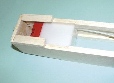
One of the reasons for including 3/16 x 1/2 doublers to strengthen the wing seat and battery access hatch aperture was to leave a void suitable for the load bearing plates required for an undercarriage. This allows the entire structure to be installed without compromising the battery area whatsoever!
All that’s required is a 1″ wide base plate of 1/16 ply, glued where shown on the plan, fitting perfectly between the two balsa doublers. If you use the removable wing option described below, these plates should be fitted right behind the hardwood or hard balsa wing securing blocks. Then, using 10swg piano wire as a width guide, glue the two 1/8 ply pieces in place to leave the piano wire a nice snug fit in the resultant groove. This exercise needs to be repeated on the other fuselage side in exactly the same position, to make sure the legs exit the fuselage at the same place. If installing the undercarriage option from the outset this can be done straight after gluing the doublers in place, allowing you to position the two opposite sides together and line up the piano wire grooves.
Bending the piano wire u/c to shape is fairly straightforward, but time taken here and the use of a good bench vice will pay dividends. To permanently fit the u/c (preferably after covering), simply glue the 1/16 ply protection plate to the bottom of the wing, file corresponding relief grooves in the bottom doublers and epoxy the undercarriage into place. Final securing is by gluing the 1/16 ply caps in place (roughing up the piano wire with abrasive paper provides a good key for maximum adhesion).
You’ll now find that the battery access hatch won’t sit in place properly, so mark the position of the undercarriage legs and (using a round file) relieve the hatch where required. If you make a neat job of this it will appear that the u/c legs simply exit the corners of the fuselage with no evidence of their origin!
Article continues below…
AT THE BACK
To complete the tail dragger type landing gear, use either a simple skid or a tail wheel. The latter is a little fiddly and vulnerable on a model of this size, but as the mounting system is the same you can make the exiting piano wire into either a skid or an axle – the choice is yours!
Cut a chunk from the rear fuselage as shown, and replicate the offcut in hardwood to fit neatly into the gap but about 1/16 narrower each side. The hardwood block must then be drilled centrally and grooved vertically at the wider end, and the 14swg piano wire piece inserted and glued into place. As mentioned above this can either become a skid or an axle, but the hardwood block must be glued very firmly into place, inset by 1/16 all round. The back end of the model is finished off by sheeting the hardwood block each side with 1/16 balsa, which is then sanded to the original shape.
READY TO ROLL
All that remains is to fit some wheels. Probably the best to consider are lightweight sponge jobs as, not only do they look good on the model, their weight and drag are more or less insignificant. As a point of interest, the addition of the complete undercarriage system adds less than 3oz (85g) to the all-up-weight of the Whizzza and thus has an almost negligible effect on flight performance.
With the u/c set in the position shown on the plan the model takes off and lands effortlessly with no tendency to ground loop, and the large rudder is extremely effective; even at low speed, the prop wash is enough to steer it! As the system is very well secured into the fuselage you can make fine adjustments to the position at the flying field by bending the legs fore or aft to find your preferred sweet spot, as long as you remember to straighten the axles again following any bending after a heavy landing!
WING REMOVAL
Due to the gap at the front of the wing, that allows the motor-to-ESC wiring to pass through, there isn’t anywhere strong enough for the usual tongue or dowels to locate. So, the method shown on the plan was developed, and this has proved totally effective and reliable. Instead of being embedded in the l.e. as normal, the dowels are located at the rear of the wing, whilst two appropriately drilled hardwood blocks are positioned at the forward end of the fuselage / wing bay to accept nylon wing bolts.
Now, since the Whizzza has only one main former it follows that this must be employed in securing the removable wing and, to this end, the first job is to glue the 1/16 ply strengthening plate where shown. The two dowels need to be recessed slightly into the underside of the wing t.e. panel and glued firmly in place with a generous amount of epoxy. When these are set, offer the wing up to the ply reinforcing plate on the former and mark where the holes need to be drilled. Once complete, elongate the holes gradually with a round file until the wing slides nicely into position but with no slop. The torque rod journal tubes should be trapped between the wing t.e. and the upper extent of the ply reinforcing plate. Check, here, that the changes havent adversely affected the operation of the torque rods or aileron linkage. If so, you may need to file relief grooves in the ply.
With the wing squarely in place (by ensuring that the wing tip to tail tip distances are equal) mark this position with a pencil line down each wing seat doubler (done from inside the battery access hatch). When gluing the wing bolt securing blocks in place make sure the wing adopts this same position!
To keep the panel in place at the front, two hardwood blocks are employed. These are glued between the wing seat and hatch doublers in the same way as the undercarriage system, but dont extend the whole way down. In the first instance they need to be drilled the whole way through, with the captive nuts glued into the bottom of each block. I had to cut away and file two flats on the circular spiked part of the captive nuts to get them to end up flush with the shape of the block, but once glued into place they fitted fine. Incidentally, if you dont have any suitable hardwood then use very hard grade balsa block – I did this on two prototypes without any problems and it was considerably easier to drill!
With both blocks complete, i.e. sporting captive nuts, fit the wing in position and drill corresponding holes through the l.e. panel. Its a good idea to dummy fit everything by screwing the nylon wing bolts down into the blocks and establish whether they contact the fuselage sides correctly, making necessary small adjustments to the holes until they do. When happy, and with the wing bolts still screwed in, generously epoxy them in place 1/16 below the wing seat surface; as the wing l.e. is profiled down to the 4mm square spruce, the blocks will lean slightly forward as shown on the plan. Hold the wing in its correct position marked by the pencil lines until the 5-minute epoxy has fully cured.
This method ensures that, when unscrewed, the nylon wing bolts will always return nicely to the position they were in when the blocks were glued in place. On the upper wing surface you need to reinforce the area of l.e. panel where the nylon wing bolts go through – this can be done either by using the nylon spreading washers / mouldings supplied with the wing bolts, a thin ply load-spreading plate or washers, or simply by soaking the surrounding area of the balsa with thin cyano.
The gap still exists for the ESC-to-motor wiring, and to either fit or remove the wing all you need to do is pull the battery and Rx wires back through their holes, flip the ESC over onto the front decking, and the wing is free to be removed – but make sure youve unplugged the aileron servo wire first!
The hidden extra with this system is that the two wing bolt blocks are perfectly positioned to help keep the flight battery in place! Battery retention is always very important, and by using some thin foam packing you can make your flight battery a nice tight push fit between these two blocks before final securing (e.g. a Velcro strap arrangement).
Article continues below…
OILY POWER
Finally, for the benefit of those who will never see the electric light, Ive developed an i.c. version of the Whizzza for .20 – .25 two-stroke power. The model is fundamentally the same but with changes at the front – as you can see from the alternative sections on the plan, the main former is slightly wider.
Start by making a firewall from good quality 1/4 (6mm) birch ply, and add the balsa strip to the top. The former is glued within the edges of the fuselage sides, but before assembly the throttle snake outer must be in place – to do this, cut an appropriate gap in the 1/8 (3mm) sheet balsa front doubler and glue the outer tube in position between the two resulting sections of the doubler. Also note that the doublers arent glued flush with the front of the fuselage sides but are instead set back 1/4 to allow for the thickness of the ply firewall.
Work out the required angle of your engine so that the silencer exhausts under the wing but wont hit the ground on landing, and when this has been established drill the engine mount, throttle snake and fuel pipe holes in the firewall.
Assemble the fuselage sides using said firewall and the main former, noting that the flat-edged triangular pieces on the top of the fuselage sides are only half the length of those on the electric version. The i.c. version has been designed for the SLEC 6oz square fuel tank which is a snug fit in the fuselage and can be secured with a dab of epoxy. Fit all the tubing at an early stage, and establish the operation of the throttle snake with the tank in position. Once installed, the thick lower deck is then glued in place.
To complete the cowling with the side cheeks its probably better to dummy fit the engine so you can get the cheek heights to correspond with the silencer on the right and access to the needle valve assembly on the left. A curved scrap insert on the top fairs everything in nicely.
SETTING UP
Fuel proof the entire nose area before covering, and locate the plumbing; tank pressure and filler pipes can either exit the front upper deck or come through the engine mount centre, along with the fuel delivery pipe. Theres plenty of space for the r/c gear, simply arrange the servos and Rx battery to achieve the correct C of G. I would advise a mini servo for the throttle, but you can use standard jobs for the rudder and elevator in line astern, with another standard servo for the ailerons.
At 2 lb 7oz (1120g) the i.c. Whizzza actually weighs slightly more than the electric version – testament to the advances in motor and Li-Po battery technology over the last few years – and explains the slight performance advantage that the electric version exhibits.
Set the model up with control movements as shown on the main plan and youre ready to go. In truth, the only noticeable difference between the i.c. and electric versions is the fact that the electric Whizzza can be launched vertically, whereas the i.c. version needs a straight and level chuck. Mind you, on a .20 two-stroke the turn of speed is quite good, and on a .25 its sparkling!
As part of the i.c. versions development, the Warwick Model Flyers, through the efforts of club secretary Richard LeMare, decided to adopt the Whizzza as their 2006 club model. Of the 60-strong club, no fewer than 20 members jumped at kits immediately; this figure is steadily creeping up as others see the aeroplane in action. Their intention is to have six organised events throughout the year with various disciplines – speed, duration, aerobatics, pylon, spot landing etc., and from the feedback received so far, everyone is absolutely delighted with the design. It’s proved to be rugged, reliable and very easy to live with despite some extreme engines being fitted to some examples!
A big thanks to Richard LeMare and the Warwick team, as their enthusiasm for the design and feedback has helped me develop the i.c. version of the Whizzza into the well-sorted item presented here.
ON FINALS
So thats about it. You’ve got the plans for a cracking 600 BL sport model that has fantastic performance even on budget brushless electric flight gear, the facility to add a strong and effective u/c and, what’s more, you can give it a removable wing if you so desire. Of course, there’s also the i.c. version if you’re still not convinced of the benefits that electric flight has to offer! Any (or all) of these modifications can be made without affecting the fundamental design, so all that remains is for you to build one.
Datafile
Name: Whizzza
Model type: Electric aerobatic
Designed by: Nigel Hawes
Wingspan: 42” (1067mm)
Fuselage length: 36” (914mm)
Wing area: 315 sq. in.
All-up weight: 40oz (maximum)
Wing loading: 18oz / sq. ft.
C of G: 80 – 95mm from root l.e.
Motor: 600-size brushless
Battery: 3s 2000mAh Li-Po
Control functions: Aileron, elevator, rudder, throttle
Control deflections: Aileron ±1⁄2”, elevator ±1⁄2”, rudder ±1”
Hardware: Canopy available from Vortex Vac-Forms tel. 01162 207080. Sticker sheets from M.troniks tel. 01943 461482